A plate-and-frame filter press consists of three main assemblies: the frame, the closing mechanism, and the filtration assembly. A complete system also includes supporting equipment such as the feed pump, piping, filtrate collection system, and electrical controls to handle material delivery, solid-liquid separation, and machine operation.
The frame supports the filter plate pack. The closing mechanism uses manual, mechanical, or hydraulic force to clamp the plates and frames together. The filtration assembly uses filter plates, frames, and filter cloths to separate solids from liquid. These components work together during feeding, filtration, cake formation, and discharge.
Main components of the filter press frame
The frame is the load-bearing structure of a plate-and-frame filter press. Its main components include the thrust plate, closing plate, and main beams. Depending on the equipment design, it may also include support bases, guide rails, and other connecting components.
Thrust plate
The thrust plate is installed at the fixed end of the frame and connected to the support structure and foundation. It carries the reaction force generated by the closing mechanism and provides fixed support for the filter plate pack.
The thrust plate generally has connections for feed, filtrate, and other process lines. Some machines use a central feed arrangement with corresponding corner ports in the filter plates for washing liquid inlets, filtrate outlets, or other process connections.
Equipment configured for closed filtrate discharge, filter cake washing, or membrane squeezing may also have corresponding piping connections on the thrust plate. The number and position of these connections depend on the plate design and process requirements.
Closing plate
The closing plate, also called the movable pressure plate, is installed at the moving end of the frame and connected to the closing mechanism.
During closing, the plate moves along the main beams or guide rails toward the thrust plate. It compresses the filter plates and frames to form sealed filtration chambers.
During cake discharge, the closing plate retracts to provide space for plate separation and cake removal. Some presses have rollers or sliding supports on both sides of the closing plate to allow smooth movement along the main beams.
Main beams
The main beams are the primary load-bearing members of the filter press. They connect the fixed and moving ends of the frame and support the filter plate pack and closing plate.
During operation, the beams must withstand the reaction force generated when the plate pack is clamped. Their structural strength, rigidity, and connection design affect the overall stability of the equipment.
For corrosive operating environments, suitable protective coatings, stainless steel cladding, or other protective treatments may be selected according to the application. The base material and corrosion protection method must meet the equipment's structural and operating requirements. Polypropylene and rigid polyvinyl chloride are more commonly used for filter plates and corrosion-resistant components rather than as general-purpose main beam materials.
Types of filter press closing mechanisms
The closing mechanism moves the closing plate and clamps the filter plates and frames together to form sealed filtration chambers. Depending on the drive method, closing systems are generally classified as manual, mechanical, or hydraulic.
Manual closing mechanism
A manual closing mechanism generally uses a screw jack or hand-operated screw assembly. The operator turns a handle to move the screw, which pushes the closing plate forward.
As the screw rotates, the closing plate moves toward the thrust plate and compresses the filter plate pack. Reversing the operation retracts the closing plate and allows the plates to be separated.
This arrangement has a relatively simple structure and does not require a separate hydraulic power system. It is suitable for applications with lower closing force and equipment capacity requirements.
Mechanical closing mechanism
A mechanical closing mechanism generally consists of a drive motor, gearbox, gear transmission, screw, and nut assembly.
During closing, the motor drives the screw through the gearbox and gear train. The screw rotates within the fixed nut and produces axial movement, pushing the closing plate forward to compress the filter plate pack.
When the required closing force is reached, the overload protection device stops the motor according to the current or another control signal. Some mechanical systems use a self-locking screw drive to maintain the clamping position. This depends on the screw design and transmission arrangement.
During opening, the motor runs in the reverse direction and retracts the closing plate. When the plate reaches its specified retracted position and activates the travel limit switch, the drive system stops.
Hydraulic closing mechanism
Hydraulic closing is a common arrangement for plate-and-frame filter presses. Its main components include a hydraulic power unit, hydraulic cylinder, piston, piston rod, piping, and control valves.
The hydraulic power unit generally consists of a drive motor, oil pump, reservoir, relief valve, directional control valve, pressure gauge, and associated piping.
During closing, the hydraulic pump delivers pressurized oil to the cap end of the cylinder, pushing the piston and piston rod forward. The piston rod is connected to the closing plate, which then compresses the filter plate pack.
When the system reaches the specified pressure, the relief valve limits the system pressure. The pressure gauge or pressure sensor displays the operating pressure. Once the required closing condition is reached, the closing movement stops.
Some hydraulic filter presses use automatic pressure-holding control. An electrical contact pressure gauge or pressure sensor monitors the system pressure. When the pressure drops below the preset lower limit, the hydraulic pump starts automatically to restore it. The pump stops when the pressure reaches the upper limit. This arrangement maintains the required clamping force during filtration.
When the press needs to open, the directional control valve changes the oil flow direction. Pressurized oil enters the corresponding cylinder chamber, causing the piston and closing plate to retract.
Main components of the filtration assembly
The filtration assembly is responsible for solid-liquid separation. Its main components are filter plates, filter frames, and filter cloths. Depending on the process, it may also include membrane plates and specially designed plates for filter cake washing.
Filter plates
Filter plates generally have grooved surfaces that support the filter cloth and collect filtrate during filtration.
After passing through the cloth, filtrate enters the drainage grooves and flows out through the plate outlet ports. The plates must also withstand filtration pressure and the clamping force applied to the plate pack. Their structural strength, sealing surfaces, and material properties must therefore meet the equipment requirements.
Common plate materials include polypropylene and other corrosion-resistant materials. Selection depends on the chemical properties of the feed material, operating temperature, and filtration pressure.
Filter frames
Filter frames are installed between adjacent filter plates and provide the space in which filter cake accumulates.
When the press is closed, the plates and frames form sealed filtration chambers. The feed slurry enters the chambers, where solid particles are retained by the filter cloth and gradually accumulate. The liquid passes through the cloth and exits through the drainage structure in the plates.
Frame thickness affects chamber volume and cake thickness. Different frame specifications can be selected according to the filtration requirements.
Filter cloths
Filter cloths are the primary filtration media in a plate-and-frame filter press. They retain solid particles while allowing liquid to pass through.
The cloth material, pore size, and weave structure affect filtration speed, filtrate quality, and cake dewatering performance. Selection should take into account the pH, temperature, particle size, and chemical composition of the feed material.
Common filter cloth materials include polypropylene, polyester, and nylon. The appropriate material depends on the actual operating conditions.
During installation, the cloths should be laid flat, with the feed and drainage openings correctly aligned. Wrinkles, displacement, or misaligned openings can interfere with filtration.
Membrane plates
Membrane plates can be used when the process requires a lower filter cake moisture content.
A membrane plate consists of a supporting structure and a flexible membrane. A squeeze cavity is formed behind the membrane. After conventional feed filtration, pressurized water or another specified squeezing medium can be introduced into the cavity. The membrane expands and compresses the filter cake, forcing out additional moisture.
Membrane plates are a specific equipment configuration and are not included in every conventional plate-and-frame filter press.
Filtration and washing methods
In addition to conventional pressure filtration, a plate-and-frame filter press can be configured with different filtrate discharge and filter cake washing systems.
Open filtrate discharge
With open filtrate discharge, each filter plate generally has an individual filtrate outlet. Some machines use nozzles or taps beneath the plates.
Filtrate flows directly out of the individual outlets. Operators can observe the liquid from each plate and identify damaged filter cloths or abnormal filtration conditions.
Closed filtrate discharge
With closed filtrate discharge, the drainage ports of the filter plates connect to form an internal collection channel. Filtrate is collected inside the press and discharged through a common pipe.
This arrangement reduces direct exposure of the filtrate to the surrounding environment. It is suitable for materials that are volatile, corrosive, or require enclosed collection.
Open and closed discharge describe the filtrate collection arrangement. They do not change the basic principle by which plates and frames form the filtration chambers.
Single-direction filter cake washing
When filter cake washing is required, wash liquid can be introduced after the filtration stage.
In single-direction washing, the liquid enters through a designated wash inlet, passes through the filter cloth and cake, and leaves through the corresponding filtrate outlet. The washing liquid moves through the cake in one specified direction. This method requires a suitable plate and piping configuration.
Two-direction or cross-flow filter cake washing
Two-direction washing is generally carried out in two stages.
First, wash liquid enters from one side, passes through the filter cake, and exits from the opposite side. The inlet and outlet arrangement is then changed so that the liquid passes through the cake in the reverse direction.
Changing the direction of flow can improve the uniformity of cake washing.
Both single-direction and two-direction washing require suitable plate channels, wash plate arrangements, and piping and valve configurations. Open or closed discharge determines how the resulting liquid is collected. These are separate aspects of the filter press design.
Some filter presses can also be equipped with compressed air blow-down systems to remove residual liquid from the filter cake or internal channels. Whether this function is available, and whether steam can be used, depends on the equipment design, material temperature resistance, and process requirements. Neither should be treated as a standard feature of every filter press.
How the main components work together
During operation, the three main assemblies perform different functions.
The frame supports the machine and withstands the reaction force generated during closing. The closing mechanism moves the closing plate and clamps the filter plates and frames together to form sealed filtration chambers.
The feed pump then delivers slurry into the chambers. The filter cloth retains solid particles, while the filtrate passes through the filter plates and exits through the drainage system. After filtration, the closing force is released. The plates are separated manually or by a plate-shifting system, and the filter cake is discharged before the next cycle begins.
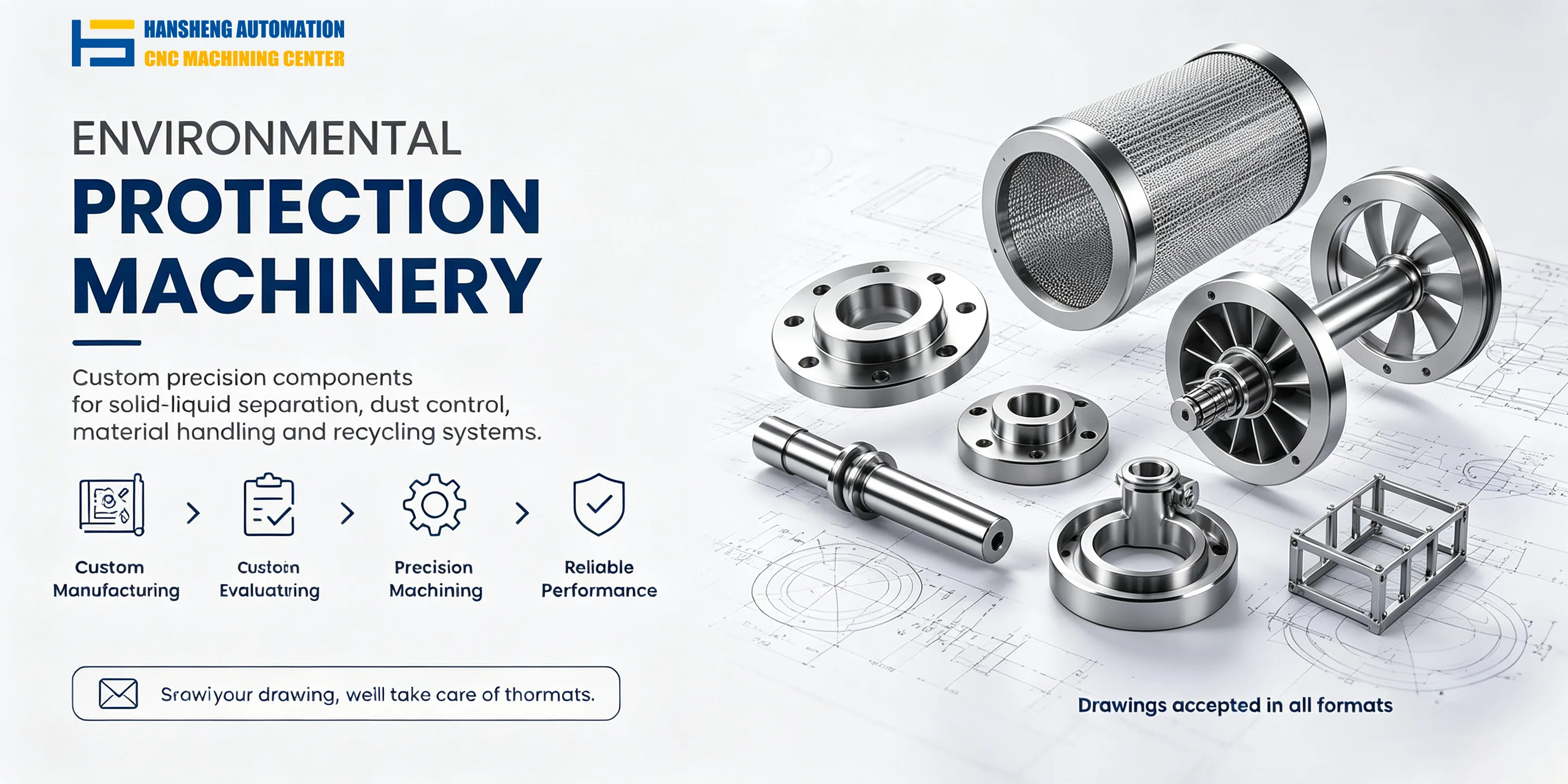
In addition to filtration components and associated mechanical parts, our precision machining services cover other manufacturing industries. Hansheng Automation manufactures custom yacht equipment components, precision structural parts for remote-control racing cars, and non-standard components for filling and tobacco packaging machinery according to customer-supplied drawings. Both single-piece and small-batch precision machining are supported.