An automatic plate-and-frame filter press relies on coordinated operation of the hydraulic system, automatic plate-shifting mechanism, cake discharge equipment, and pneumatic controls. A fault in any of these systems may prevent the plates from closing properly, reduce the closing pressure, interrupt plate movement, or lower the air pressure used for center-feed blowback.
This article examines four common operating problems: insufficient plate closing pressure, unsynchronized plate movement, abnormal hydraulic system noise, and low air pressure during center-feed blowback. It also outlines the likely causes and inspection procedures for each condition.
Insufficient Filter Plate Closing Pressure
Symptoms
After the automatic filter press starts its closing cycle, the closing plate may move normally, but the hydraulic system fails to reach the preset clamping pressure or cannot maintain it.
Other symptoms may include premature hydraulic pump shutdown, abnormal pressure gauge readings, and inadequate sealing between the filter plates. In severe cases, filtrate or slurry may leak between the plates during filtration.
Possible Causes
Low hydraulic oil level: If the oil level in the hydraulic reservoir falls below the specified range, the pump may not receive an adequate oil supply. Loose hydraulic connections, deteriorated seals, or other leakage points can also cause continued oil loss.
Reduced hydraulic pump output: Internal pump wear, a blocked suction line, or air entering the inlet side can prevent the hydraulic system from generating the required closing pressure.
Incorrect plate position detection: A limit switch or position sensor installed in the wrong position may cause the control system to identify the closing plate as being at its target position too early. The closing sequence may then stop before the required movement is completed. Position detection and pressure detection are separate control functions. Adjusting a limit switch cannot replace proper pressure control.
Incorrect closing pressure setting: A pressure setting below the specified value, or inaccurate readings from a pressure sensor or electrical contact pressure gauge, may cause the hydraulic pump to stop prematurely.
Hydraulic valve or cylinder leakage: An incorrectly adjusted relief valve, a check valve that does not close properly, or damaged piston seals can prevent the system from building or maintaining pressure.
Solutions
First, check the hydraulic oil level and condition. If the level is low, replenish the system with the specified hydraulic oil and inspect hoses, fittings, and cylinder seals for leakage.
If the oil level is normal but the pressure remains insufficient, inspect the pump, suction line, and filtration elements. Repair or replace the pump if internal wear or reduced output capacity is confirmed.
Check the mounting position and signal status of the plate limit switches and position sensors. Confirm that the control system correctly identifies the closing plate position. The pressure gauge and pressure sensor should also be checked for accuracy.
Finally, verify the hydraulic closing pressure setting against the manufacturer's specifications. Inspect the relief valve, check valve, and cylinder seals for abnormal operation or leakage. Do not increase the hydraulic pressure arbitrarily, as this may overload the filter plates, cylinder, or frame.
Unsynchronized Filter Plate Movement During Closing
Symptoms
During the automatic closing sequence, the plates may move unevenly or fail to reach their designated positions in the specified sequence. In some systems, the discharge trolley may not return to its home position, preventing the closing cycle from continuing.
Some automatic presses use position interlocks between the plate-shifting mechanism and the discharge trolley. If the trolley has not returned to its home position, the control system may prevent the next closing operation.
Possible Causes
Discharge trolley not in its home position: After cake discharge, the trolley may fail to return completely. The home position sensor cannot then provide the required signal, preventing the automatic closing sequence from continuing.
Discharge trolley drive failure: Wear, jamming, or damage to the motor, gearbox, drive chain, or gears can interfere with trolley movement.
Faulty limit switch or position sensor: The trolley may have reached its home position, but a faulty limit switch or sensor fails to send the correct signal to the control system.
Electrical control signal problems: Loose wiring, poor terminal connections, faulty relays, or abnormal PLC signals may prevent the actuators from following the programmed sequence.
Incorrect plate alignment or guide problems: Plates that are not properly aligned on the rails, or guide rails affected by sludge accumulation, wear, or deformation, can create uneven resistance during closing.
Solutions
First, check whether the discharge trolley has returned completely to its original position. Make sure that residual filter cake, foreign material, or mechanical obstructions are not preventing movement.
If the trolley cannot return, inspect the drive motor, gearbox, and transmission components. Repair any mechanical obstruction or drive fault.
If the trolley is in position but the closing sequence still cannot proceed, inspect the limit switch and position sensor. Confirm that the control system receives the correct home position signal.
For electrical control faults, inspect the relays, terminal connections, control wiring, and PLC input and output signals. Qualified electrical personnel should carry out repairs where necessary.
Also check the filter plate arrangement and guide rails. Remove residual sludge from the rails and inspect the rollers and guide components for wear.
On equipment with dual-side drives or other synchronized movement arrangements, inspect the drive operation and position feedback on both sides according to the equipment design. Do not change mechanical synchronization settings without first confirming the cause of the fault.
Abnormal Noise in the Hydraulic System
Symptoms
After the hydraulic power unit starts, the pump or motor may produce unusual noise and vibration. These symptoms may also occur with pressure fluctuations, increased oil temperature, or unstable closing movement.
Possible Causes
Loose fasteners: Loose connections on the hydraulic pump, motor base, piping supports, or mounting bolts can generate vibration and abnormal noise during operation.
Excessive hydraulic oil viscosity: Oil with a viscosity outside the specified range, or oil that becomes too viscous in a low-temperature environment, increases resistance in the pump suction line.
Restricted pump suction: A blocked suction line, excessive filter resistance, or low reservoir oil level may cause pump cavitation and abnormal noise.
Air entering the hydraulic circuit: Loose suction-side fittings, damaged seals, or air mixed into the oil can cause pump noise and pressure fluctuations.
Pump or bearing wear: Worn pump components, bearings, or other drive parts may produce continuous noise and vibration.
Poor motor and pump alignment: Incorrect coupling installation, shaft misalignment, or loose connections may cause mechanical vibration and noise.
Relief valve malfunction: A stuck valve spool or an incorrect pressure setting may generate abnormal flow noise or pressure pulsation.
Solutions
Inspect the mounting connections of the hydraulic pump, motor, base, and piping supports. Tighten loose fasteners and check that the coupling is correctly installed.
Verify that the hydraulic oil grade and viscosity meet the equipment requirements. If low ambient temperature causes excessive oil viscosity, use an approved preheating method to bring the oil to its specified operating temperature. Never use an open flame to heat the reservoir or hydraulic lines.
Check the reservoir oil level, suction piping, and filtration elements. Clean blocked components and ensure that the pump receives an adequate oil supply.
If air has entered the hydraulic circuit, inspect suction line fittings and seals, repair the leakage points, and bleed the system according to the manufacturer's procedure.
If mechanical noise continues, inspect the internal pump components, bearings, and relief valve. Repair or replace worn or damaged parts as required.
Low Air Pressure During Center-Feed Blowback
Symptoms
After filtration is complete, the press starts the center-feed blowback sequence, but the compressed air pressure is too low to remove residual sludge from the center feed hole and feed channel.
The blowback cycle may take longer, the feed channel may not be cleaned properly, or slurry may remain in the feed pipe. These conditions can affect the next feeding cycle and subsequent cake discharge.
Center-feed blowback generally uses compressed air to enter the central feed channel of the plate pack and push residual sludge back into a designated return line or sludge collection system. The actual air direction and discharge route depend on the filter plate and piping design.
Possible Causes
Insufficient compressor output: The air compressor may be shut down, tripped, or unable to maintain the required discharge pressure.
Insufficient air receiver capacity: Low receiver pressure, inadequate stored air volume, or simultaneous demand from other pneumatic equipment may cause the supply pressure to drop during blowback.
Incorrect pneumatic regulator setting: A regulator setting that is too low, an inaccurate pressure gauge, or a faulty regulator can reduce the blowback pressure.
Solenoid valve or control circuit failure: A damaged solenoid, stuck valve spool, faulty relay, or open control circuit may prevent the blowback air path from opening fully.
Leaking or restricted air lines: Loose fittings, damaged seals, bent tubing, or blocked filters can restrict compressed air flow.
Mechanical valve malfunction: A three-way valve, shut-off valve, or other pneumatic valve may be stuck, worn, or unable to open fully.
Blocked center feed channel: Dried sludge or solid particles may obstruct the center feed hole or internal passage. In this case, normal supply pressure alone may not restore the blowback function.
Solutions
First, check the compressor operating condition, discharge pressure, and supply capacity. Confirm that the compressed air supply meets the requirements of the blowback system. If the compressor has tripped, identify and correct the electrical or mechanical fault before restarting it.
Inspect the air receiver pressure, supply lines, and other pneumatic equipment to determine whether the system has insufficient air capacity during peak demand.
Next, check the pneumatic regulator, pressure gauge, and air filters. Confirm that the pressure setting and gauge readings are correct. Clean or replace blocked or damaged filter elements.
Inspect the solenoid valves, three-way valves, and control wiring. Confirm that the valves open and close according to the PLC sequence. Clean, repair, or replace valves with stuck spools or damaged seals.
Check the blowback line fittings, seals, and piping for leaks or restrictions. Repair leakage points and clear blockages.
If the air supply reaches the specified pressure but the center channel still cannot be cleared, inspect the center feed ports and internal passages for sludge buildup. Do not mistake a mechanical blockage for insufficient air supply pressure.
The blowback pressure and duration must follow the equipment manufacturer's specifications. Do not increase compressed air pressure arbitrarily to overcome a blockage, as this may damage the piping, filter plates, or valves.
Maintenance and Safety Precautions for Automatic Filter Presses
Automatic filter presses contain hydraulic, mechanical, electrical, and pneumatic systems. Each system must be placed in a safe condition before maintenance.
Hydraulic maintenance: Stop the machine and release hydraulic pressure. Confirm that no residual pressure remains before removing hoses, valves, or cylinder components.
Filter plate and discharge mechanism maintenance: Isolate the power supply and make sure that the automatic plate-shifting mechanism and discharge trolley cannot move unexpectedly.
Compressed air system maintenance: Shut off the air supply and release residual pressure in the lines before removing pneumatic valves, regulators, or air hoses.
Electrical control maintenance: Power supply, relays, limit switches, and PLC signals should be inspected by qualified personnel. Do not bypass safety interlocks without an approved procedure.
Post-maintenance testing: After replacing components or adjusting settings, carry out unloaded tests and functional checks according to the equipment procedure. Confirm that plate closing, clamping, plate shifting, and center-feed blowback operate correctly before returning the press to service.
Regular inspection of hydraulic oil levels, pressure sensors, plate-shifting mechanisms, pneumatic valves, and control wiring helps identify problems early and reduce unplanned downtime.
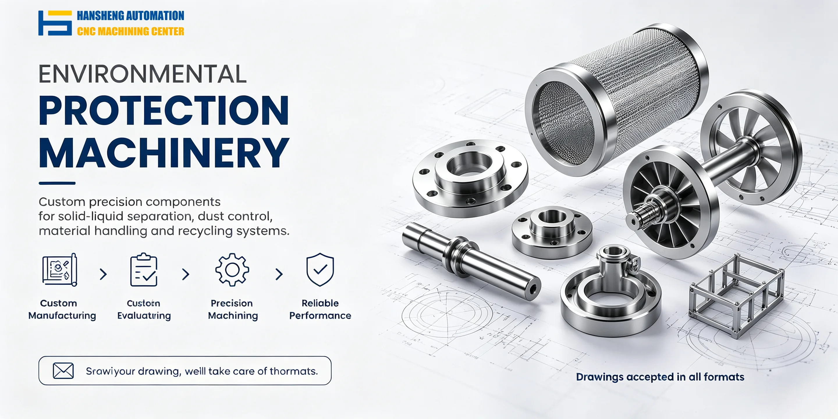
In addition to mechanical components used in filter press equipment, Hansheng Automation provides precision machining services for several manufacturing industries. We manufacture custom functional components for tobacco packaging and filling machinery, as well as precision parts for yacht equipment and structural components for remote-control racing cars, according to customer-supplied drawings. Both single-piece and small-batch precision machining are supported.