The standard technical solution for six-axis loading and unloading robots focuses on adapting to target workstation conditions. It covers four modules: hardware selection, motion planning, safety protection, and deployment and commissioning. The solution supports stable loading and unloading operations with a payload range of 3–120 kg and repeatability of 0.02–0.1 mm, suitable for batch production scenarios such as machine tools, stamping, and injection molding.
I. Hardware Selection
(A) Robot Body Selection
Payload: a margin of at least 20% should be reserved based on workpiece weight plus gripper weight. For example, if the workpiece weight is 50 kg and the gripper weight is 10 kg, a model with a rated payload of 70 kg or above should be selected.
Repeatability: choose according to workpiece assembly tolerance. For precision electronic assembly, a 0.02 mm class model is used; for general machine tool loading and unloading, a 0.1 mm class model is acceptable.
Reach: the robot must cover the workpiece pick-up position, placement position, and safety avoidance range. For conventional machine tool loading and unloading, a reach of 1440–2000 mm is usually sufficient.
(B) End Effector Selection
Suction cup type: suitable for flat and thin-walled workpieces. It works with a vacuum generator and pressure sensor, with a leakage detection threshold to avoid gripping failure.
Gripper type: suitable for irregular and heavy workpieces. Pneumatic or electric grippers can be used, integrating position feedback modules to ensure proper gripping.
Quick-change disc: used in multi-variety workpiece switching scenarios, with docking repeatability ≤0.05 mm, enabling fixture changeover within 1 minute.
(C) Peripheral Equipment
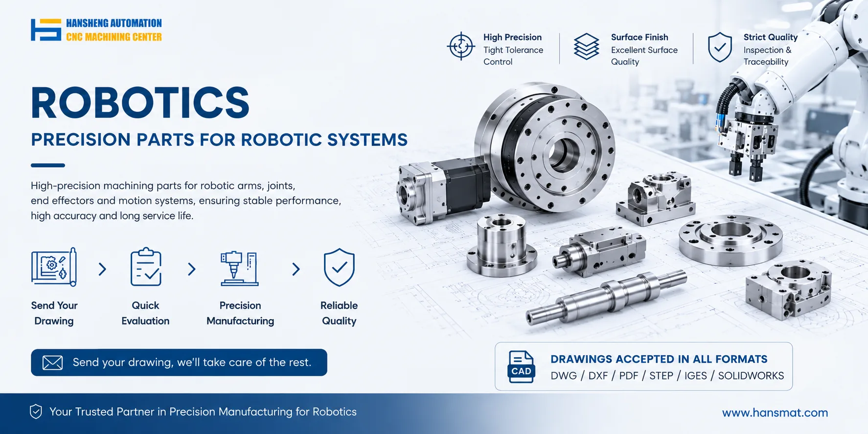
Workpiece positioning fixture: adopts a datum block plus limit pin structure with repeatability ≤0.03 mm to ensure consistent gripping position. For these positioning fixtures and related non-standard components, Hansheng Automation provides custom machining services based on customer drawings, supporting both prototype and batch production.
Material conveying equipment: matched to robot cycle time. For batch scenarios, roller conveyors or bin racks can be used; for small batches, fixed material tables are suitable.
Safety protection facilities: aluminum profile and acrylic safety fences, combined with safety light curtains, emergency stop buttons, and audible-visual alarms.
II. Motion Planning and Program Architecture
(A) Motion Path Planning
Linear motion (L command) is used for pick-and-place operations to ensure path accuracy and stable cycle time; joint motion (J command) is used for empty travel to reduce non-working time.
Reserve safety clearance: minimum clearance between robot and workstation equipment or fence ≥50 mm, and 1–2 mm docking allowance for workpiece gripping.
(B) Program Logic Writing
The main program calls five subprograms: initialization, picking, transferring, placing, and reset.
Integrate exception handling logic: including stop alarm and reset procedures for workpiece jamming, gripping failure, power interruption, etc.
Cycle time optimization: overlap robot operation timing with workstation processing timing, for example, prepare the next workpiece during machine tool processing.
III. Safety Protection Design
(A) Hardware Safety Configuration
Independent safety controller: physically isolated from the robot controller, monitoring emergency stop and safety light curtain signals in real time.
Safety protection devices: opposed safety light curtains at station entrances, triggering immediate safety stop when interrupted.
Collision detection: enable the robot body's built-in torque limiting function to decelerate and stop urgently upon collision detection.
(B) Software Safety Rules
Speed classification: manual teaching mode speed ≤250 mm/s; automatic production mode speed not exceeding 80% of rated speed.
Limit protection: set both soft limits and hard limits to prevent the robot from exceeding its working range.
Alarm linkage: when an abnormality is triggered, simultaneously stop workstation equipment and activate audible-visual alarm.
IV. Deployment and Commissioning Process
On-site installation: robot base is fixed by concrete pouring, with anchor bolt pull-out force ≥10 kN to offset vibration. Alignment deviation between peripheral equipment and robot ≤0.1 mm.
Accuracy calibration: use laser tracker to complete joint zero-point calibration, ensuring repeatability meets selection parameters.
Teaching verification: manually teach pick-up and placement points, verify collision-free path, and adjust end-effector orientation for reliable gripping.
Cycle time test: run 100 products continuously and confirm cycle time deviation ≤±0.5 s.
Safety verification: simulate personnel intrusion and workpiece jamming to confirm safety functions are effective.