A six-axis industrial robot typically adopts a serial multi-joint articulated arm configuration. It consists of three core parts: the mechanical structure unit, the drive and transmission unit, and the control and sensing unit. Through six independent rotary joints, the robot achieves full six-degree-of-freedom motion, allowing it to perform tasks in any spatial orientation.
1. Mechanical Structure Unit
The robot uses a serial link-type rigid structure, in which each joint is connected by a rotary pair from the base to the end effector.
Base: serves as the supporting foundation of the entire robot, fixed to the floor, worktable, or mobile platform. The first-axis drive and braking components are integrated inside.
Waist assembly: connects the base and the upper arm, corresponding to axis 1. It can rotate 360° and drives the entire arm to swing horizontally.
Arm assembly: includes the shoulder, upper arm, elbow, and forearm. The shoulder corresponds to axis 2 and drives the upper arm in pitch motion. The elbow corresponds to axis 3 and drives the forearm in pitch motion. Together they adjust the spatial height and forward-backward position of the arm.
Wrist assembly: consists of three rotary joints corresponding to axes 4, 5, and 6. These joints control the orientation of the end effector. Axis 4 rotates the wrist around the forearm axis, axis 5 swings the wrist up and down, and axis 6 rotates the end effector. Through coordinated movement, the end effector can be adjusted to any spatial orientation.
End effector: a quickly replaceable working component such as a pneumatic gripper, welding torch, or vacuum suction cup, mounted directly on the flange of axis 6.
2. Drive and Transmission Unit
Each joint is equipped with independent power and transmission components to ensure motion accuracy and rigidity.
Servo motors: serve as the power source for each axis. AC servo motors are the mainstream configuration, providing precise speed and torque output.
Reducers: are core transmission components. Heavy-load joints such as axes 2, 3, and 5 usually adopt RV reducers for high rigidity and large reduction ratios. Light-load joints such as axes 1, 4, and 6 usually adopt harmonic reducers for compact layout and high-precision reduction.
Transmission connectors: power is transmitted from the motor to the joint shaft through synchronous belts or high-precision gear sets. Some compact models use direct-drive motors to eliminate intermediate transmission components, further improving motion accuracy.
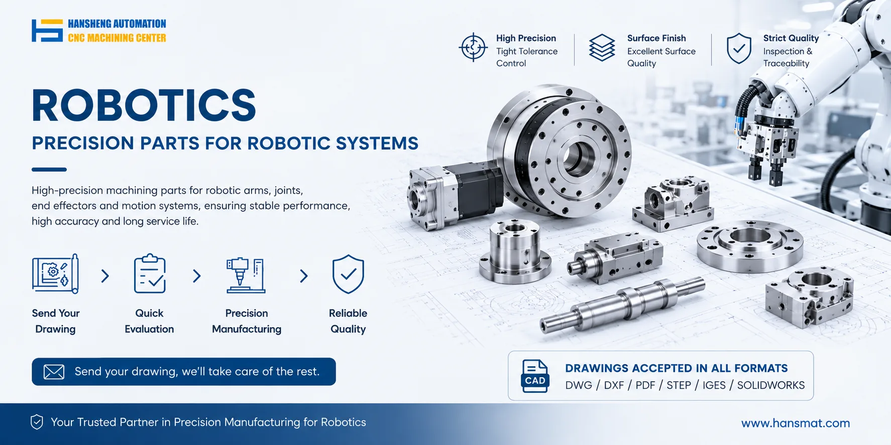
For non-standard parts within these drive systems, such as adapter flanges, transmission shafts, and reducer mounting housings, Hansheng Automation provides custom machining services based on customer drawings, supporting both prototype development and small-batch production.
3. Control and Sensing Unit
Control cabinet: integrates the motion controller, servo drives, power modules, and I/O interfaces. It interprets operation programming instructions, outputs motion signals for each axis, and collects feedback data from joint encoders and torque sensors to achieve closed-loop precise control.
Teach pendant: serves as the human-machine interaction terminal, used for manual teaching of operation paths, modification of motion parameters, and real-time monitoring of robot status.
Optional sensing components: some high-end models integrate vision cameras and force sensors to assist with high-precision positioning, force-controlled grinding, and other complex tasks.
All joints have rated motion ranges and load limits. Operation and maintenance must strictly follow the manufacturer's technical documentation to avoid collisions or structural overload.