The feed hopper is an important part of a waste incinerator's feeding system. It receives waste from the storage bunker and transfers it to the downstream feeding equipment. The hopper must accommodate waste with varying sizes and compositions, including materials that can wrap around components or form bridges during discharge. Its design affects material flow, feeding consistency, and the safe operation of the incinerator.
In common municipal solid waste incineration systems with moving grates, the feed hopper works with the feeding chute, hydraulic ram feeder, and furnace isolation devices. Depending on the furnace design and project requirements, the feeding system may include the following components.
Main Hopper Structure
The feed hopper is generally fabricated from welded steel plates. Its overall shape is typically funnel-shaped or designed with sloping walls to facilitate waste discharge. The upper section receives waste from the overhead crane, while the lower section connects to the feeding chute or feeding equipment, providing a buffer for subsequent material delivery.
Municipal solid waste may contain hard materials such as metal, glass, and construction debris. These materials can cause impact damage and wear on the hopper walls. The internal surfaces therefore need adequate wear resistance. Wear-resistant steel plates or wear-resistant cast iron may be used for protection in areas exposed to heavy abrasion.
The feed hopper and lower chute must also withstand the loads generated by accumulated waste, together with impact and friction during feeding. Components close to the furnace require additional protection against high temperatures and flashback. Depending on the design, this protection may include water-cooled double-wall construction, membrane walls, or refractory linings.
Hopper Gates and Feeding Mechanisms
Gates and feeding mechanisms control the transfer of waste into the incinerator. They must also prevent hot flue gas or flames from traveling back from the furnace into the feeding system.
Common components include:
Maintenance isolation gate: Used to isolate the feeding passage during inspection and maintenance. Its location and configuration depend on the equipment layout.
Feed shut-off gate: Usually installed near the connection between the feeding chute and the furnace. It can close during start-up, shutdown, or abnormal operating conditions to limit air exchange between the furnace and the external feeding system and reduce the risk of flashback.
Feeding mechanism: Transfers waste from the hopper into the furnace continuously or intermittently. Common designs include hydraulic ram feeders, hydraulic pushers, chain feeders, and screw feeders. The feeding rate can be adjusted according to the incinerator's operating load.
The shut-off gate and feeding mechanism perform different functions. Not every component that controls waste discharge should be classified as an adjustable gate. The actual arrangement depends on the furnace type and feeding method.
Structural Measures to Prevent Waste Bridging
Municipal solid waste typically contains a mixture of plastics, textiles, wood, paper, and other discarded materials. Some of these materials are flexible and can become entangled or compacted inside the hopper. This may form a bridge that interrupts waste discharge.
To maintain continuous feeding, the hopper dimensions, wall angles, and outlet geometry must be designed to allow bulky waste to pass through while reducing the risk of bridging and blockages.
For materials that are prone to bridging, auxiliary devices may be installed depending on the equipment design. These include:
Hydraulic bridge breakers: Hydraulic cylinders drive rods or movable components back and forth to loosen compacted waste and improve material discharge.
Movable hopper bottoms: Reciprocating or vibrating floor sections help prevent waste from accumulating at the bottom of the hopper.
Mechanical agitators: Rotating or reciprocating components break up entangled or compacted waste.
These devices are not standard features on every incinerator feed hopper. Their use should be determined according to waste composition, hopper geometry, and actual operating conditions.
Fire Protection and Ventilation Systems
The waste bunker and feeding system must account for risks such as waste fermentation, localized heat buildup, and fire propagation. Appropriate fire protection and ventilation systems are therefore required.
Fire Protection Equipment
Depending on the project design, fire protection systems may include fire detectors, automatic water spray systems, water cannons, and foam suppression equipment. Some installations also provide foam nozzles or fire water connections above the feed hopper to respond to fires in this area.
The location and arrangement of fire protection equipment should take into account the layout of the waste bunker, feed hopper, hydraulic drive units, and furnace. Nozzle locations and quantities should not be treated as universal requirements for all installations.
Ventilation and Negative Pressure Control
During storage, municipal solid waste can generate odors, dust, and gases such as methane. A common arrangement extracts air from the waste bunker area and sends it to the incinerator through the primary air fan for use as combustion air.
This extraction system maintains slight negative pressure in the waste bunker and waste reception area, helping prevent odors and dust from escaping. Whether the extracted air is used as primary air, secondary air, or both depends on the waste calorific value and the overall incinerator design.
Negative pressure control mainly applies to the waste bunker and reception area. Installing an extraction opening inside the feed hopper alone is not sufficient to control odors throughout the entire feeding area.
Level Monitoring and Automatic Control
Continuous waste supply requires information about the amount of material accumulated inside the hopper.
Depending on the equipment layout, radar level sensors, ultrasonic level sensors, or other suitable detection devices can be used to monitor the material level.
The signals can be sent to the central control system and linked to the overhead crane, feeding mechanism, and incinerator control system. When the material level reaches a preset condition, the system can issue commands to replenish or stop feeding. This helps prevent hopper overfilling, material shortages, and uneven feeding.
Sensor locations should account for waste accumulation patterns and interference from dust and moisture to avoid incorrect readings that could affect automatic control.
Insulation and Measures to Prevent Blockages
In cold regions, waste with a high moisture content may freeze, affecting material flow and feeding continuity. For installations exposed to freezing conditions or specific material adhesion problems, insulation, freeze protection, or heating measures may be required.
For example, thermal insulation can be installed on the outside of the hopper under certain operating conditions. Steam heating may also be used to reduce material freezing and buildup.
However, insulation and steam heating coils are not standard components of every waste incinerator feed hopper. Their use depends on the local climate, waste properties, and operating conditions.
Main Design Parameters of a Waste Incinerator Feed Hopper
The dimensions, capacity, and structural arrangement of a feed hopper depend on the incinerator capacity, physical properties of the waste, and feeding method. The following factors should be considered during equipment design and selection.
Effective Capacity
The hopper needs sufficient buffering capacity to accommodate the difference between intermittent waste loading by the overhead crane and continuous feeding into the incinerator.
It is important to distinguish between the capacity of the waste bunker and that of the feed hopper. The European Commission's Waste Incineration BAT Reference Document states that municipal solid waste bunkers typically have a storage capacity equivalent to approximately 3 to 5 days of plant operation. The actual capacity depends on local conditions and the characteristics of the waste. This figure applies to the waste bunker, not to feed hoppers as a general design requirement.
Structural and Wear-resistant Materials
The hopper body can be manufactured from steel plates with sufficient structural strength. Areas exposed to impact and friction require appropriate wear-resistant materials based on the expected wear conditions.
Wear-resistant steel plates and wear-resistant cast iron can be used in selected high-wear areas. Materials such as Q345B, NM360, and NM400 may be considered during engineering design. The final selection depends on structural loads, wear resistance, weldability, and the operating environment. These grades should not be treated as fixed material requirements for every hopper.
Hopper Wall Angle
The wall angle affects waste discharge and the risk of bridging. The design should consider waste shape, moisture content, friction characteristics, and degree of compaction when determining the wall angle and outlet dimensions.
An internal wall angle greater than 60°, as mentioned in the original material, may serve as a reference for certain designs. It is not a universal requirement for all waste incinerator hoppers. When processing waste containing large amounts of plastic film, textiles, or other materials prone to entanglement, the hopper geometry also needs to account for their flow behavior.
Custom Machining for Waste Incineration Equipment
The design of a waste incinerator feed hopper must address material reception, continuous feeding, prevention of bridging, wear protection, and operational safety. The hopper body, gates, feeding mechanism, and auxiliary control systems need to work together to reduce blockages and feeding interruptions and maintain stable incinerator operation.
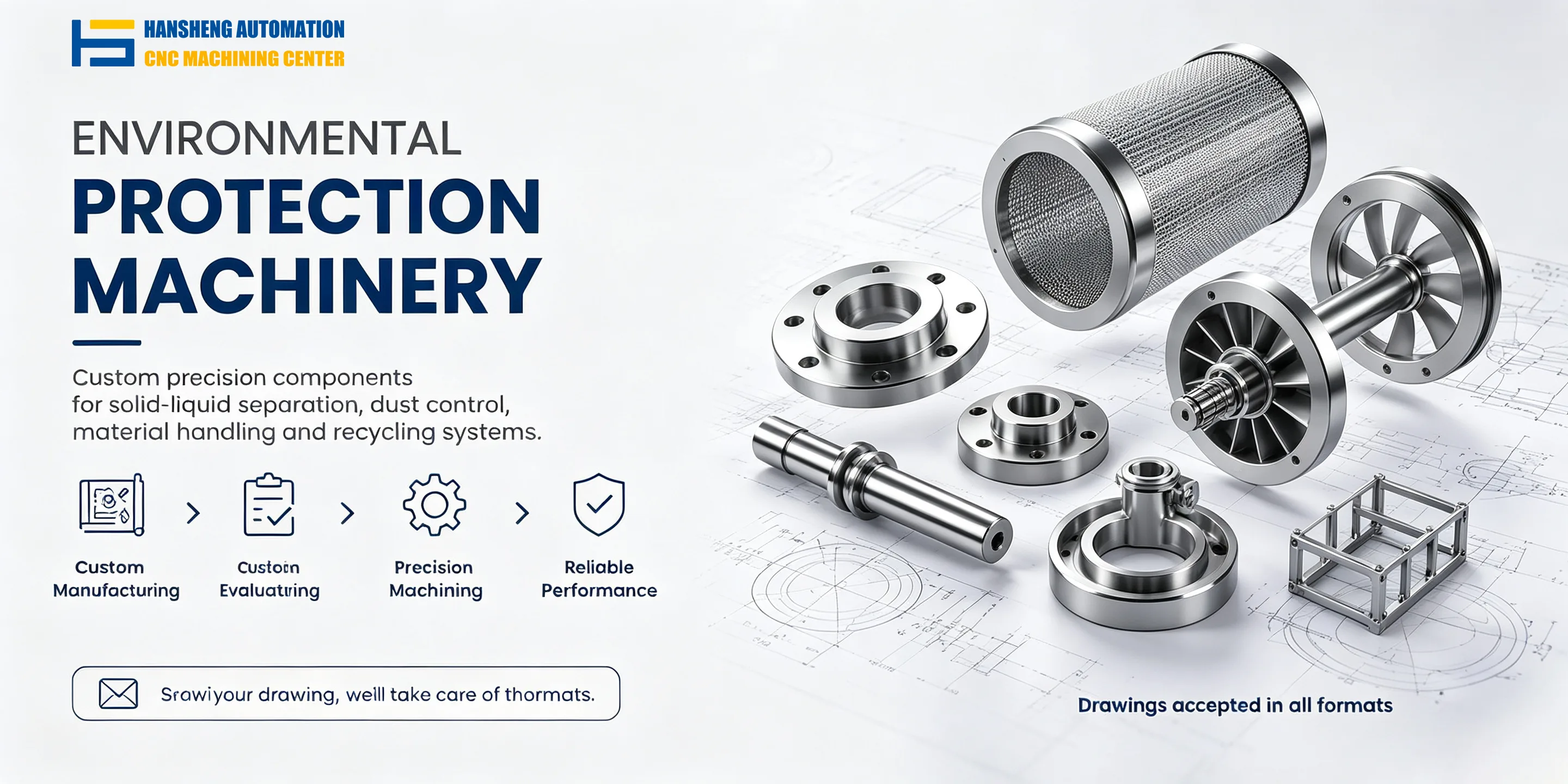
For mechanical components used in waste incineration and other environmental protection equipment, we provide custom precision machining based on customer-supplied drawings. Hansheng Automation also manufactures non-standard components for tobacco packaging machinery and filling machinery, as well as precision structural parts for yacht equipment and radio-controlled racing cars. Both single-piece and small-batch machining are available according to component dimensions and assembly requirements.