Municipal solid waste incineration power generation converts the combustible components of waste into heat, which is then recovered through a waste heat boiler and converted into electricity by a steam turbine generator. The complete process includes waste reception and storage, incineration, heat recovery, steam power generation, flue gas treatment, and bottom ash and fly ash management.
These systems operate together throughout the production process. The waste reception and storage system supplies a steady feed to the furnace. The incinerator converts waste into high-temperature flue gas, and the waste heat boiler recovers the heat. The flue gas treatment system controls pollutant emissions, while the residue handling system recovers usable materials and manages the remaining waste.
Waste Reception and Storage System
Waste reception and storage are the first stages of an incineration power plant. They involve incoming waste inspection, unloading, storage, and mixing to provide relatively consistent feed conditions for the incinerator.
Waste Reception and Unloading
When waste collection vehicles enter the plant, they are weighed on a weighbridge. The plant checks the waste source, type, and relevant transportation information according to its acceptance procedures. Waste that does not meet the acceptance requirements must be inspected and handled according to the plant's management procedures.
Accepted vehicles enter an enclosed unloading hall and discharge their loads into the waste bunker through designated unloading bays. The hall is generally equipped with sealed unloading doors and a negative pressure ventilation system to limit the release of odors and dust during unloading.
Waste Storage and Mixing
The waste bunker is generally constructed from reinforced concrete and enclosed to prevent uncontrolled emissions. A leachate collection system is installed inside the bunker.
Storage capacity is determined according to the incinerator's rated capacity, waste transportation conditions, and equipment maintenance requirements. China's Ministry of Ecology and Environment recommends in its Technical Guidelines for Municipal Solid Waste Treatment that the effective bunker volume should be designed to accommodate approximately 5 to 7 days of the rated municipal solid waste incineration capacity. Actual project designs should account for site-specific conditions.
An overhead grab crane is usually installed above the bunker. Operators use the grab to turn and mix waste from different areas, helping make its composition and calorific value more uniform. The crane then transfers the waste to the incinerator feed hopper.
Leachate generated during waste storage is collected through drainage channels and a collection system at the bottom of the bunker. It is then sent to a leachate treatment facility. Depending on water quality and process requirements, treated leachate may be recycled or disposed of in compliance with applicable requirements.
The waste bunker is generally maintained under slight negative pressure. Extracted air can be supplied to the incinerator as primary combustion air, where high temperatures help destroy odorous compounds. When the incinerator is shut down or the primary air system is unavailable, backup odor control measures may be required according to the plant design.
Waste Incineration System
The incineration system is the main process unit of the power plant. Its main components include the feeding equipment, incinerator, grate drive system, combustion air supply system, and bottom ash discharge equipment. Its main function is to burn the combustible components of waste and produce high-temperature flue gas for heat recovery.
Incinerator Types and Waste Feeding
Moving grate incinerators are widely used in municipal solid waste treatment. They can handle waste with complex compositions and fluctuating moisture content and calorific value.
Circulating fluidized bed incinerators are also used in some projects. They generally require waste pre-treatment, including shredding and screening, or the use of processed refuse-derived fuel (RDF).
The overhead grab crane transfers waste into the feed hopper. Waste then passes through the feeding chute to the ram feeder. A hydraulic pushing mechanism moves the waste onto the grate according to a preset stroke and feeding speed.
The feeding chute and isolation devices must provide adequate sealing to limit excessive air ingress into the furnace and reduce the risk of hot flue gas flowing back into the feeding system.
Combustion on the Moving Grate
A moving grate incinerator generally has three main combustion zones: drying, combustion, and burnout. Each zone performs a different function.
Drying zone: Heat radiation and primary air raise the waste temperature and evaporate moisture, preparing the material for combustion.
Combustion zone: Combustible components burn at high temperatures with an adequate oxygen supply, releasing heat.
Burnout zone: Residual char and incompletely burned combustible materials continue to burn until the bottom ash meets the required loss on ignition criteria.
The grate is generally divided into several independent air chambers. Primary air enters from below the grate, and the air supply to each chamber can be adjusted according to waste distribution and combustion conditions.
Secondary air is injected into the upper part of the furnace to mix with combustible gases. This improves combustion conditions and helps control products of incomplete combustion, including carbon monoxide.
Combustion Temperature and Gas Residence Time
During municipal solid waste incineration, furnace temperature, flue gas residence time, and oxygen conditions must be controlled to ensure adequate combustion and reduce the formation of dioxins and related pollutants.
Under GB 18485-2014, the Standard for Pollution Control on the Municipal Solid Waste Incineration, including its amendment, the furnace must be designed and operated to maintain a flue gas temperature of at least 850°C for no less than 2 seconds above the cross-section where the final secondary combustion air is injected.
The current administrative requirements for automatic monitoring at municipal solid waste incineration plants also specify that the five-minute average temperature measured by furnace thermocouples must not be below 850°C during normal operation.
These requirements form part of combustion control. Furnace geometry, air distribution, and operating controls must work together to maintain the required temperature and residence time. Combustion quality cannot be evaluated by temperature alone.
Bottom Ash Discharge and Cooling
After combustion on the grate, the remaining bottom ash is discharged from the end of the grate. It is commonly transferred through a bottom ash discharger into a water quench tank or another cooling unit.
The cooled bottom ash is then conveyed to downstream treatment equipment. The cooling method and discharge temperature depend on the equipment design and subsequent processing requirements. A temperature of 60°C should not be treated as a universal control limit for every project.
Waste Heat Recovery and Power Generation System
High-temperature flue gas from waste combustion contains recoverable thermal energy. The waste heat boiler uses heat exchangers to recover this energy and convert boiler feedwater into superheated steam. The steam then drives a turbine generator to produce electricity.
Heat Exchange in the Waste Heat Boiler
High-temperature flue gas enters the waste heat boiler from the incinerator and passes through radiant and convective heat transfer sections.
Boiler feedwater is preheated in the economizer before entering the evaporation system. As the water absorbs heat, it produces steam. After steam-water separation, the steam passes through the superheater to reach the operating conditions required by the turbine.
A waste heat boiler generally includes an economizer, evaporator, and superheater. The arrangement and structure of these heat transfer sections depend on the boiler design.
Common main steam conditions in Chinese municipal solid waste incineration power plants include 4.0 MPa and 400°C for medium-temperature, medium-pressure systems. Some plants use medium-temperature, sub-high-pressure systems operating at 6.4 MPa and 450°C. The selected parameters depend on waste calorific value, boiler efficiency, turbine design, and project investment conditions.
Steam Turbine Power Generation
Superheated steam from the waste heat boiler enters the steam turbine through the main steam pipeline. As the steam expands and its pressure and temperature decrease, it drives the turbine rotor.
The turbine is connected to a generator through a coupling. The generator converts mechanical energy into alternating-current electricity.
The generated electricity passes through the electrical system and a step-up transformer before being supplied to the grid, subject to grid connection requirements. Some of the electricity is used within the plant to operate fans, pumps, conveying equipment, and other auxiliary systems.
Condensate and Feedwater Circulation
Steam leaving the turbine enters the condenser, where the cooling system converts it back into water. The condensate passes through the required water treatment and deaeration stages before the feedwater pump raises its pressure and returns it to the waste heat boiler.
Boiler makeup water generally undergoes demineralization to control impurities and mineral content, reducing the risk of scale formation and corrosion on heat transfer surfaces.
Electricity Generation per Ton of Waste
Electricity generation depends on several factors, including the lower heating value of the waste, moisture content, ash content, grate and boiler efficiency, steam turbine parameters, and plant auxiliary power consumption.
As an industry reference for domestic grate-fired municipal solid waste incineration plants, gross electricity generation is approximately 305 to 420 kWh per ton of waste. After deducting electricity consumed by the plant, the net electricity exported to the grid is approximately 250 to 350 kWh per ton. These figures are indicative estimates. Actual performance varies considerably between projects.
Some plants with a stable heat demand can also operate in combined heat and power (CHP) mode. Part of the steam is supplied for industrial processes or district heating, improving overall energy utilization.
Flue Gas Treatment System
Flue gas from waste incineration may contain particulate matter, acid gases, nitrogen oxides, heavy metals, and dioxins. The flue gas treatment system uses denitrification, acid gas removal, adsorption, and dust collection to control pollutant emissions.
The actual treatment configuration depends on flue gas composition, emission requirements, and project design. Common treatment processes in China include selective non-catalytic reduction (SNCR), semi-dry or dry acid gas removal, activated carbon injection, and fabric filtration. Some plants also use wet scrubbing or selective catalytic reduction (SCR).
Flue Gas Cooling and Denitrification
After leaving the furnace, flue gas enters the waste heat boiler, where heat is recovered through heat exchange.
An SNCR system is generally installed in the furnace or another suitable high-temperature gas section. Ammonia water or urea solution is injected into the flue gas. Within the appropriate temperature range, the reducing agent reacts with nitrogen oxides to form nitrogen and water.
Projects with more stringent nitrogen oxide removal requirements may also use an SCR system in the downstream flue gas treatment line. SCR uses a catalyst to promote the reaction between nitrogen oxides and a reducing agent. Its installation location must account for the flue gas temperature and overall system design.
Semi-dry and Dry Acid Gas Removal
Semi-dry acid gas removal commonly uses a rotary atomizer or another type of spray drying reactor. The equipment atomizes a hydrated lime slurry into the flue gas. The alkaline absorbent reacts with acidic gases such as hydrogen chloride and sulfur dioxide to form calcium salts.
Dry acid gas removal generally involves injecting powdered hydrated lime or sodium bicarbonate into the flue gas. These absorbents react with the acidic pollutants.
Depending on project requirements, semi-dry and dry processes may be combined to improve acid gas removal efficiency.
Activated Carbon Adsorption
Activated carbon is generally injected into the flue gas duct through a dedicated feeding system. Its large specific surface area allows it to adsorb certain dioxin compounds and heavy metals such as mercury.
The activated carbon, together with the adsorbed pollutants, travels with the flue gas into the fabric filter, where it is captured along with other particulate matter.
Fabric Filtration
After acid gas treatment and activated carbon adsorption, the flue gas enters the fabric filter. The filter bags capture fly ash, reaction salts, and activated carbon particles containing adsorbed pollutants.
Dust removal efficiency depends on filter media performance, filtration velocity, flue gas temperature, and cleaning method. Fly ash and reaction residues collected by the fabric filter must be collected and handled separately.
Particulate emissions must comply with GB 18485-2014 and its amendment, as well as applicable local emission standards. A concentration of 10 mg/Nm³ should not be treated as a universal emission limit for all facilities.
Wet Scrubbing and Flue Gas Reheating
Some plants install a wet scrubber downstream of the fabric filter to remove residual acid gases and certain soluble pollutants. Wet scrubbing systems generally require circulating slurry, mist eliminators, and wastewater treatment facilities.
When wet scrubbing or another low-temperature treatment process is used, the design must account for acid dew point corrosion, stack discharge conditions, and visible plume control. Some projects use gas-to-gas heat exchangers or steam heaters to reheat the treated flue gas.
The reheating temperature depends on flue gas humidity, dew point, stack design, and local emission requirements. A fixed temperature of 80°C should not be applied to every system.
Bottom Ash and Fly Ash Treatment
The main solid residues from waste incineration are bottom ash and fly ash. They form in different parts of the incineration system and have different compositions and contamination characteristics. They therefore require separate treatment and disposal methods.
Bottom Ash Treatment
Bottom ash discharged from the end of the grate is cooled and transferred to screening and separation equipment.
Screening, magnetic separation, and other sorting processes can recover ferrous metals and certain non-ferrous metals. After metal recovery, the remaining bottom ash may be used as a raw material for construction products, road materials, or other applications, depending on its composition, leaching characteristics, and product quality requirements.
Bottom ash recovery requires appropriate quality testing and environmental safety assessment. It should not be used directly in construction or road projects without the required treatment and testing.
Fly Ash Collection and Treatment
Fly ash mainly consists of fine particles collected by equipment such as fabric filters during flue gas treatment. It may contain heavy metals, soluble salts, and dioxins.
Municipal solid waste incineration fly ash is managed as hazardous waste under the applicable regulations. Common treatment methods include cement-based solidification, chemical stabilization, chelating agent treatment, and other approved processes designed to reduce contaminant leaching.
Treated fly ash must still be disposed of according to applicable environmental management requirements.
Under GB 16889-2024, the Standard for Pollution Control on Municipal Solid Waste Landfill Sites, municipal solid waste incineration fly ash can enter a separate landfill zone only when it meets the specified conditions. Its dioxin content must be below 3 μg TEQ/kg, and the concentrations of hazardous substances in the leachate prepared according to HJ/T 300 must be below the limits specified in the standard.
Fly ash compliance cannot be determined solely by whether solidification has been completed. Test results for pollutants and the acceptance requirements of the final disposal facility must also be considered.
Leachate and Other Wastewater Treatment
Waste storage generates leachate, while wet flue gas treatment and other production operations may also produce wastewater. Municipal solid waste incineration plants therefore require wastewater collection and treatment systems.
Leachate is generally collected, pre-treated, and subjected to further treatment. Depending on water quality and project requirements, the treated water may be reused or disposed of in compliance with applicable standards.
Wastewater from wet flue gas treatment requires treatment according to its pollutant composition to prevent heavy metals, salts, and other contaminants from entering the external water environment.
Treatment processes vary between projects and must be selected according to actual wastewater quality, reuse requirements, and discharge standards.
Online Monitoring and Safety Control Systems
Municipal solid waste incineration power plants use automatic monitoring and process control systems to track furnace operating conditions, flue gas emissions, and key equipment parameters.
Continuous Flue Gas Monitoring
A continuous emission monitoring system (CEMS) is generally installed at the stack to monitor pollutants such as particulate matter, sulfur dioxide, nitrogen oxides, hydrogen chloride, and carbon monoxide. Depending on monitoring requirements, the system also records parameters such as flue gas flow rate, temperature, pressure, and oxygen content.
Monitoring data are transmitted to the environmental authorities' monitoring system according to the applicable requirements. The data are used for emission management and operating supervision.
Dioxins are not currently part of routine continuous CEMS monitoring. Their emission levels are generally determined by collecting flue gas samples using the prescribed sampling methods and analyzing them in a laboratory.
Process Monitoring
The incinerator and waste heat boiler are equipped with temperature, pressure, flow, and level instruments to monitor combustion conditions and steam system operation.
When furnace temperature, boiler pressure, or other critical parameters exceed their preset limits, the control system issues alarms and performs the required adjustments, interlocks, or shutdown actions according to the equipment protection logic.
Gas detection equipment can be installed in the waste bunker and other areas where gases may accumulate. Depending on the risk assessment, monitoring may cover combustible gases and hazardous gases such as methane and hydrogen sulfide.
Fire Protection and Safety Systems
Fire protection equipment is selected according to the fire risks in different plant areas. The waste bunker and unloading hall may be equipped with water cannons, automatic sprinkler systems, or other suitable fire suppression equipment. Cable rooms, electrical control rooms, and other critical areas require appropriate fire detection and suppression systems.
The incinerator, waste heat boiler, steam turbine, and auxiliary equipment also require suitable safety protection devices to control risks associated with excessive temperature, overpressure, equipment faults, and abnormal operating conditions.
Custom Machining for Waste Incineration Equipment
Municipal solid waste incineration power plants use several interconnected processes, including waste reception, combustion, heat recovery, steam generation, flue gas treatment, and residue handling. The coordinated operation of these systems determines the plant's processing capacity, energy recovery efficiency, and environmental performance.
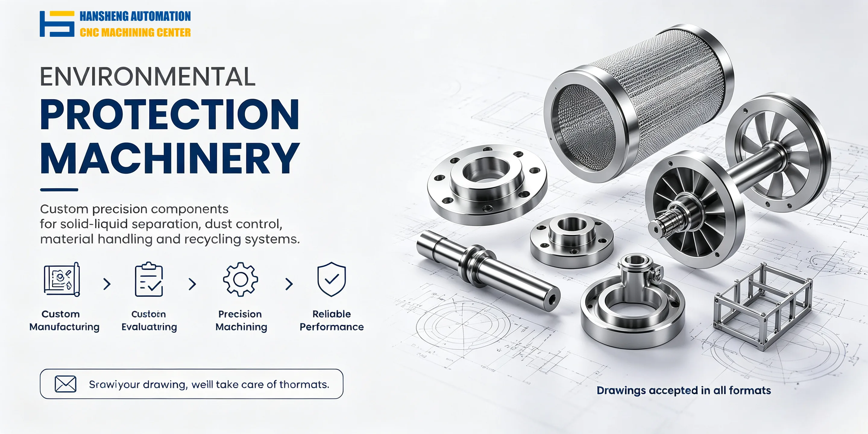
For components used in waste incineration and environmental protection equipment, we provide custom precision machining based on customer-supplied drawings. Hansheng Automation also manufactures non-standard components for tobacco packaging machinery and filling machinery, as well as precision parts for yacht equipment and structural components for radio-controlled racing cars. We support single-piece and small-batch production according to specific drawing and machining requirements.