Catalytic oxidation equipment for paint spray booth exhaust commonly combines activated carbon adsorption, thermal desorption, and catalytic oxidation. The system first captures VOCs from the exhaust using activated carbon. The adsorbed compounds are then released through a controlled desorption process and sent to a catalytic reactor for oxidation.
This arrangement is suitable for certain painting operations that generate relatively large volumes of exhaust containing low to moderate VOC concentrations. It reduces the volume of gas requiring catalytic treatment by concentrating the captured VOCs before oxidation.
The main structural features include adsorption vessels, desorption equipment, a catalytic oxidation unit, heat exchangers, fans, automatic valves, and an electrical control system.
Main Equipment Components
Activated Carbon Adsorption Vessels
The adsorption vessel is one of the main components of the system. It contains activated carbon or another suitable adsorbent that captures VOCs from the exhaust.
As the paint booth exhaust passes through the carbon bed, organic compounds are retained on the adsorbent surface. The treated air then leaves the vessel through the exhaust duct.
Activated carbon is selected for its developed pore structure and adsorption capacity. Its suitability depends on the VOC composition, concentration, gas temperature, and humidity.
An upstream filtration stage is generally required to remove paint mist and particulate matter before the exhaust enters the adsorption vessel. This prevents deposits from blocking the carbon bed and reducing its adsorption capacity.
The system also requires suitable access for inspecting and replacing the activated carbon.
Condenser and Gas-Liquid Separator
A condenser and gas-liquid separator can be included when the system uses a solvent recovery arrangement.
During steam desorption, steam carries the released VOCs out of the activated carbon vessel. The resulting steam and VOC mixture passes through a condenser, where cooling water removes heat and condenses the vapor mixture into liquid.
The condensate can then enter a separator, where immiscible organic and aqueous phases are separated. The recovered solvent can be collected for further processing or reuse, while the water phase is sent for appropriate wastewater treatment.
These components are not required in every adsorption-catalytic oxidation system. When hot-air desorption is used and the concentrated VOC stream is sent directly to the catalytic reactor, the condenser and separator may not be necessary.
The actual configuration depends on whether the process is designed to recover solvents or destroy the desorbed VOCs through oxidation.
Desorption Air Blower and Heating System
The desorption system removes VOCs accumulated in the activated carbon bed.
In a hot-air regeneration system, a dedicated blower circulates heated air through the carbon bed. The increased temperature reduces the adsorption capacity of the activated carbon, causing the captured VOC molecules to desorb and enter the concentrated exhaust stream.
Depending on the equipment design, steam or another suitable regeneration medium may also be used.
The released VOCs are conveyed to the downstream catalytic oxidation unit for treatment. After desorption, the carbon bed must be dried and cooled to the specified operating condition before it returns to the adsorption cycle.
A dedicated blower, heating element, and associated ductwork provide the required air circulation and temperature control. These components should not be confused with an aerator, which is a device used primarily in liquid treatment processes.
Main Exhaust Fan
The exhaust fan provides the airflow required to convey paint booth exhaust through the collection ductwork, pretreatment equipment, and adsorption vessels.
It must be selected according to the total system airflow and pressure drop across the filters, carbon beds, ducts, and other equipment.
Depending on the system pressure arrangement, the fan may be installed upstream or downstream of the treatment units. Its position should also account for the temperature, pollutant composition, and corrosion characteristics of the gas.
The treated exhaust is discharged through the designated outlet duct after passing through the adsorption or oxidation treatment stages.
Auxiliary Components
The system also includes several auxiliary components to control airflow, temperature, and equipment operation.
These generally include:
Automatic inlet and outlet valves for switching between adsorption and regeneration cycles.
Differential pressure instruments for monitoring the resistance of the carbon bed and filters.
Carbon bed temperature sensors and high-temperature alarm devices.
Automatic cooling or other protective arrangements for abnormal temperature conditions.
An electrical control cabinet for coordinating fans, heaters, valves, and safety interlocks.
These components help maintain stable operation and allow operators to monitor the condition of the treatment system.
Flexible Adsorption and Desorption Configurations
Single-Bed and Dual-Bed Designs
The number of adsorption vessels depends on the production schedule and the exhaust treatment requirements.
For intermittent production, a single adsorption vessel may be used when the exhaust source can be stopped or safely diverted during regeneration.
For continuous production, two or more adsorption vessels are generally used. In a typical two-bed arrangement, one vessel remains in the adsorption cycle while the other undergoes desorption, drying, or cooling. Automatic valves switch the airflow between the vessels according to the control sequence.
This arrangement allows the treatment system to continue processing exhaust while one carbon bed is being regenerated.
Depending on the system design, multiple beds may also operate in parallel to provide additional adsorption capacity or accommodate different production loads.
Pneumatic Valve Control
Pneumatically actuated valves are commonly used to switch the gas flow between adsorption vessels and the desorption circuit.
During the adsorption cycle, the valves direct untreated exhaust through the active carbon bed. When the bed approaches its specified breakthrough condition, the control system isolates it and initiates the regeneration sequence.
After desorption and cooling, the regenerated bed can return to service.
The PLC controls the valve sequence according to the operating cycle and equipment interlocks. This reduces manual switching and helps prevent incorrect airflow routing.
Catalytic Oxidation System
Catalyst Bed Design
The catalytic reactor is the main VOC destruction unit.
During desorption, the concentrated VOC stream enters the catalytic oxidation system. A heating device first raises the gas temperature to the required reaction condition.
The gas then passes through a catalyst bed, where the catalyst promotes oxidation of suitable organic compounds. Under appropriate temperature, residence time, oxygen availability, and mixing conditions, VOCs are converted primarily into carbon dioxide and water, releasing heat during the reaction.
Catalytic oxidation operates at lower temperatures than conventional thermal oxidation because the catalyst accelerates the oxidation reaction.
The catalyst type and reactor configuration must be selected according to the VOC composition and the potential presence of substances that may reduce catalyst activity.
Heat Recovery
A heat exchanger is installed to recover thermal energy from the hot gas leaving the catalytic reactor.
The recovered heat is transferred to incoming desorption air or another suitable process gas, reducing the energy required by the heating system.
During stable operation, the heat released by VOC oxidation can contribute to maintaining the reaction temperature. The amount of recoverable energy depends on the VOC loading, gas flow rate, inlet temperature, and heat exchanger design.
This heat recovery arrangement helps reduce auxiliary fuel or electrical heating demand while maintaining the required catalytic reaction conditions.
Safety and Automatic Control
Carbon Bed Temperature Monitoring
Activated carbon adsorption can generate heat, particularly when the exhaust contains compounds that undergo exothermic adsorption or oxidation reactions.
If heat accumulates inside the carbon bed, local hot spots may develop and create a fire risk.
The system should therefore include temperature monitoring at appropriate positions within the carbon bed. High-temperature alarms and automatic protective measures should be configured according to the equipment design and process safety assessment.
These measures may include isolating the affected vessel, stopping the incoming exhaust, initiating a controlled cooling or purge sequence, and activating other designated fire protection measures.
The protective sequence must be specifically designed for the adsorbent, VOC composition, and system configuration.
Electrical Control Cabinet and PLC Automation
The electrical control cabinet contains the control system for the adsorption, desorption, and catalytic oxidation processes.
A programmable logic controller (PLC) coordinates fan operation, valve switching, desorption heating, catalyst temperature control, and equipment interlocks.
Temperature sensors and pressure instruments provide operating data to the control system. When abnormal conditions occur, the PLC can activate alarms and initiate the specified protective actions.
The control system should also monitor the VOC concentration where required, particularly in the concentrated desorption stream and at the catalytic reactor inlet. This helps prevent the equipment from operating beyond its specified flammability and thermal limits.
Automatic control reduces the need for manual switching, but regular inspection of the activated carbon, catalyst, valves, fans, and electrical components remains necessary.
Compact Structure and Modular Installation
The system can be arranged as an integrated equipment package, with adsorption vessels, desorption units, catalytic oxidation equipment, heat exchangers, fans, and electrical controls connected through dedicated ductwork.
A modular configuration allows equipment layout to be adjusted according to the available installation space and production requirements.
Single-bed, dual-bed, and multi-bed arrangements can be selected according to the exhaust volume and operating schedule. The final layout should provide sufficient space for carbon replacement, catalyst inspection, valve maintenance, and routine equipment servicing.
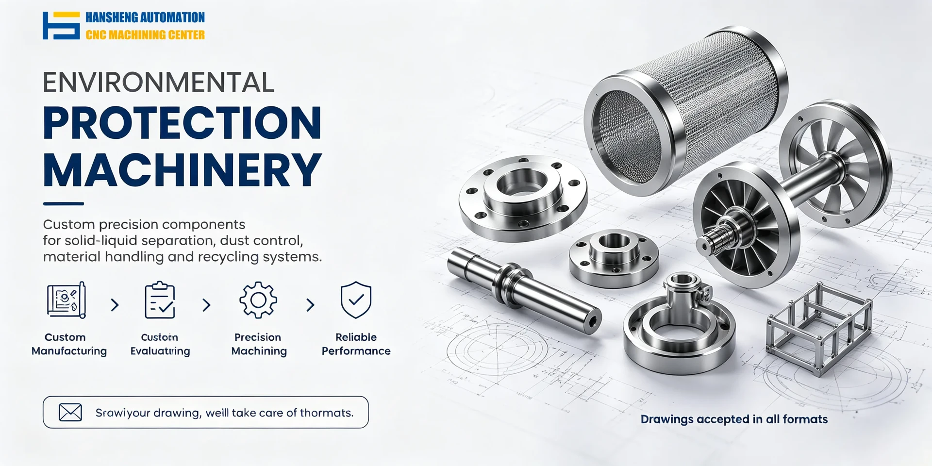
Custom Machining for Industrial Equipment Components
In addition to components used in painting and exhaust treatment equipment, Hansheng Automation provides drawing-based precision machining for non-standard industrial parts.
Our machining services also cover components for yacht equipment, remote-controlled racing cars, filling machinery, and tobacco and packaging equipment. We support single-piece and small-batch manufacturing according to customer drawings, dimensions, and assembly requirements.