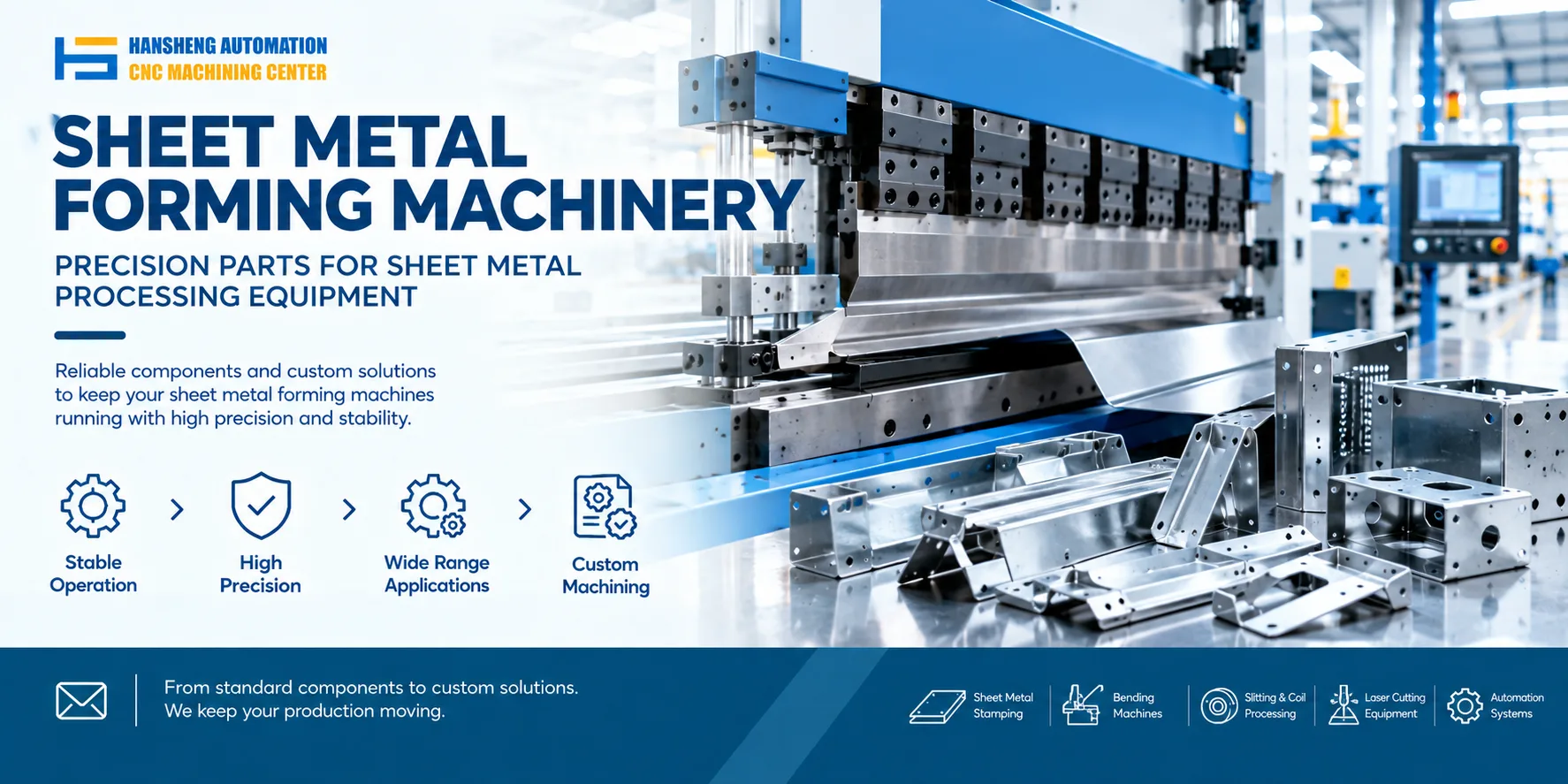
A CNC press brake uses several mechanical, hydraulic, and control components to form sheet metal accurately. The main components include the ram, worktable, synchronization system, and backgauge. Each has a specific function in controlling tool movement, supporting the workpiece, and maintaining dimensional accuracy during bending.
Ram Assembly
The ram is the main moving component of a CNC press brake. It drives the upper punch downward to bend the sheet metal and returns upward after the bending operation.
On a hydraulic press brake, the ram assembly typically includes the ram, hydraulic cylinders, and the associated position adjustment mechanism. The left and right cylinders are mounted to the machine frame. Hydraulic pressure drives the pistons, moving the ram vertically.
Some machine designs use an adjustable mechanical stop to control the ram's stopping position. On configurations equipped with motorized adjustment, the CNC system controls the setting according to the bending requirements. Correct ram positioning helps prevent tool interference and maintain the required bend angle.
Worktable
The worktable supports the lower die and provides a stable reference for the sheet metal during bending. Its rigidity and condition affect how consistently the tooling maintains its position under load.
The worktable is also associated with the machine's clamping and tooling setup. Depending on the machine configuration, additional adjustment mechanisms may be provided to support different bending requirements.
The forward and backward positioning of the sheet metal is generally handled by the backgauge rather than by moving the worktable itself. Keeping these functions separate helps clarify how the machine positions the workpiece before each bend.
Synchronization System
The synchronization system keeps the left and right sides of the ram moving together during the bending cycle. Proper synchronization helps maintain ram alignment with the worktable and supports consistent bending results across the workpiece.
In a mechanical torsion bar synchronization system, the main components include a torsion shaft, swing arms, and spherical rod-end bearings. These components form a mechanical linkage that transfers movement between the two sides of the ram.
As the ram moves, the torsion shaft and connecting components help coordinate its movement. This arrangement has a relatively simple mechanical structure. The actual synchronization method depends on the press brake design, as some machines use hydraulic or other control systems instead.
Backgauge Mechanism
The backgauge positions the sheet metal before bending. By setting the distance between the backgauge fingers and the tooling, the operator can control the flange dimension and repeat the same positioning across multiple workpieces.
A backgauge mechanism may include a drive motor, chain transmission, two screws, and guide rails. The motor transmits motion through the chain drive to move the screws and backgauge assembly. The CNC controller sets the target position and controls the motor movement according to the programmed dimensions.
Depending on the machine design, travel limit switches may be installed at the front and rear positions to prevent the backgauge from moving beyond its permitted range. Correct adjustment of the backgauge is important for maintaining dimensional consistency and reducing positioning errors.
Custom Precision Machining for Industrial Equipment
Hansheng Automation provides custom precision machining based on customer drawings for industrial applications. Our machining work also covers components for yacht equipment and RC racing cars, along with nonstandard parts used in tobacco packaging and filling machinery. Each component is manufactured according to the supplied drawing and the specific dimensional and structural requirements.