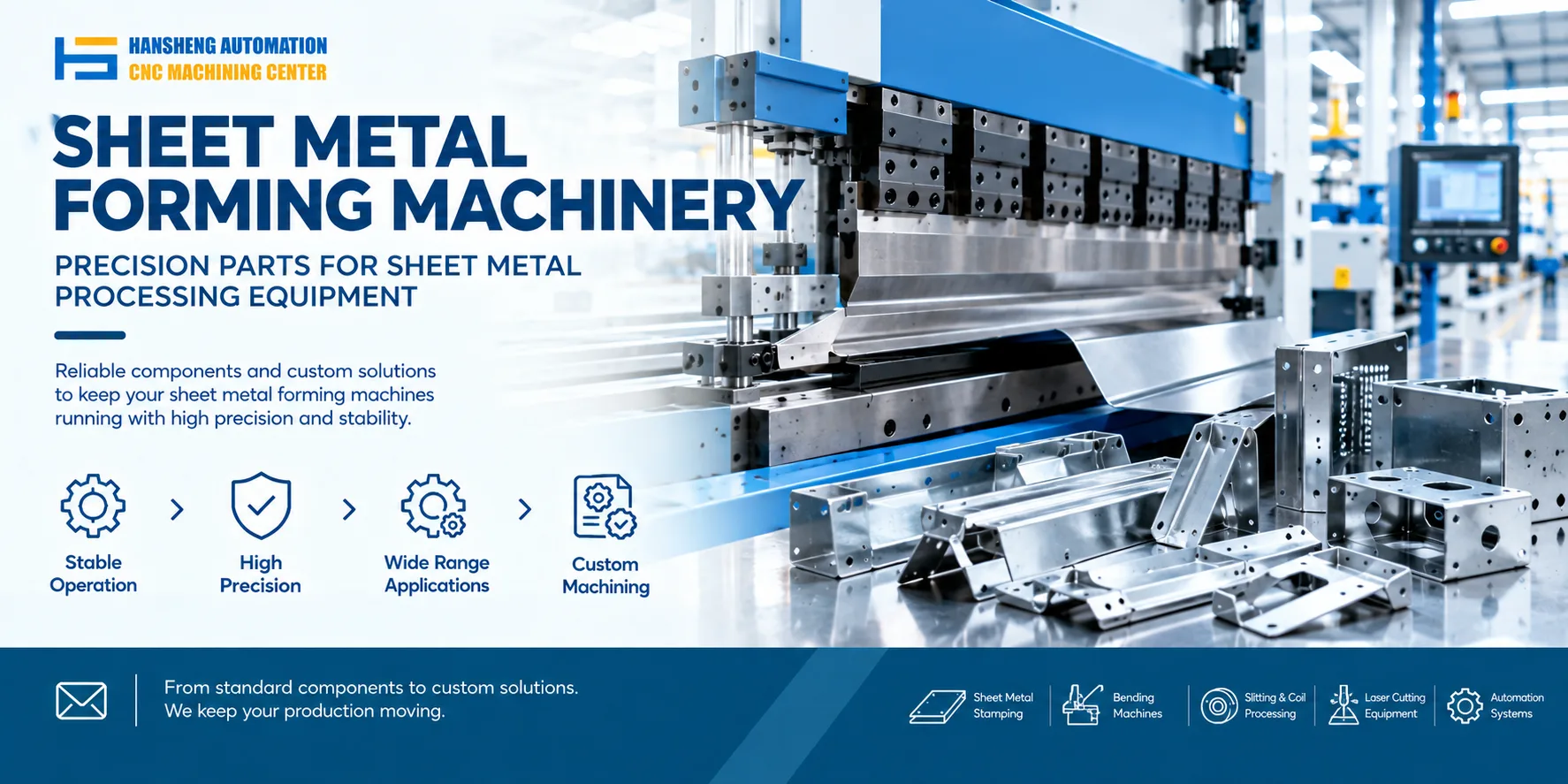
Large bend angle errors on a CNC press brake can result from problems with the crowning system, loose tooling, inconsistent ram positioning, incorrect component installation, material variation, or inaccurate position feedback. Before changing machine parameters, identify whether the angle deviation is consistent across the bend, varies along its length, or changes between bending cycles. This helps narrow down the cause and avoid unnecessary adjustments.
Check the crowning cylinder and compensation system
If the crowning cylinder cannot return fully to its zero position, the actual compensation may differ from the programmed value, resulting in bend angle errors.
Inspect the cylinder seals, hydraulic pressure stability, and mechanical return mechanism for leakage, unstable operation, or binding. Replace damaged seals or adjust the hydraulic system when necessary, following the machine manufacturer's maintenance procedures.
Inspect the quick-clamp wedges
Loose wedges in the quick-clamping system can shift the tooling from its intended position and affect bending accuracy.
Check the wedge locking bolts and confirm that the tooling is seated correctly. If any fasteners are loose, secure them according to the manufacturer's specifications and verify the tooling reference surfaces before resuming production.
Verify ram bottom dead center repeatability
If the ram reaches a different bottom dead center position during successive bending cycles, the forming conditions will vary and the bend angle may change.
Review the CNC controller's recorded position data to identify possible drift. Inspect the clearance between the ram and its guide rails, as well as the transmission accuracy of the synchronization shaft and related drive components.
If the mechanical stops or CNC position parameters require adjustment, follow the machine manufacturer's calibration procedure. Do not compensate for an underlying mechanical or feedback fault by repeatedly changing the programmed bending depth.
Check the installation of the bow plate
Incorrect bow plate installation can distribute the load unevenly across the worktable and cause local deformation. One possible problem is a mounting screw reaching the bottom of its hole before the plate is properly secured.
Check the bow plate installation against the machine's assembly requirements. Verify its level and seating, ensure that the fasteners apply even clamping force, and confirm that the mounting arrangement does not create unintended contact or localized stress.
Correct installation helps maintain the intended support conditions and compensation performance.
Check sheet metal consistency
Variations in sheet thickness, material grade, and internal stress can change springback and affect the final bend angle.
Measure the sheet thickness before processing and verify the material grade against the specified material requirements. Spectral analysis can be used when material composition needs to be confirmed. If residual stress is suspected, assess the material and processing requirements before considering stress-relief measures such as pre-stretching or annealing. These treatments should not be applied automatically without confirming their suitability for the material and finished part.
Adjust the CNC controller's springback compensation according to the actual material properties and test bend results.
Secure the linear scale and verify its feedback signal
A loose optical linear scale, also referred to as a grating scale, can produce unreliable position feedback. The controller may then report a ram position that differs from the actual position.
Inspect the scale mounting bracket for rigidity and check whether the fixing bolts have loosened. Verify signal stability using the controller's diagnostic functions, where available. If the signal remains unstable, inspect the readhead clearance and alignment according to the manufacturer's specifications. Replace the scale or correct the installation if necessary.
Improve positioning accuracy
Adjust the proportional valve zero offset
An incorrect proportional valve zero offset can cause a mismatch between the controller's command and the hydraulic system's response, affecting ram positioning.
Use the manufacturer's specified test equipment and calibration procedure to check the valve's input and output characteristics. Adjust the zero offset only after confirming the fault and ensuring that the setting falls within the permitted range.
Correct bottom dead center and return stroke problems
If the ram begins its return stroke before reaching the programmed bottom dead center, inspect the ram load sensor, acceleration and deceleration settings, and back-pressure valve pressure.
Dynamic testing can help identify whether the problem originates from sensor feedback, hydraulic response, or motion control settings. Qualified service personnel should make the necessary adjustments and verify that the ram reaches the required position consistently before returning.
Maintain consistent bending accuracy
Regular inspections help identify changes in machine condition before they cause repeated production errors.
Establish a daily inspection routine and record relevant parameters, including crowning cylinder movement and bottom dead center repeatability.
Train operators to follow consistent procedures when changing tooling, positioning sheets, and clamping workpieces.
Check CNC parameters regularly and adjust compensation settings based on measured bending results rather than repeated trial and error.
Allow the machine to warm up when ambient temperature changes significantly or when the manufacturer's operating procedure requires it. This helps reduce the effects of temperature-related dimensional changes.
Custom precision machining for industrial equipment
Hansheng Automation provides custom precision machining based on customer drawings for a range of industrial applications. Our work includes precision components for yacht equipment and RC racing cars, as well as nonstandard parts for tobacco packaging and filling machinery. Each component is manufactured according to the supplied drawings and the specific dimensional and structural requirements.