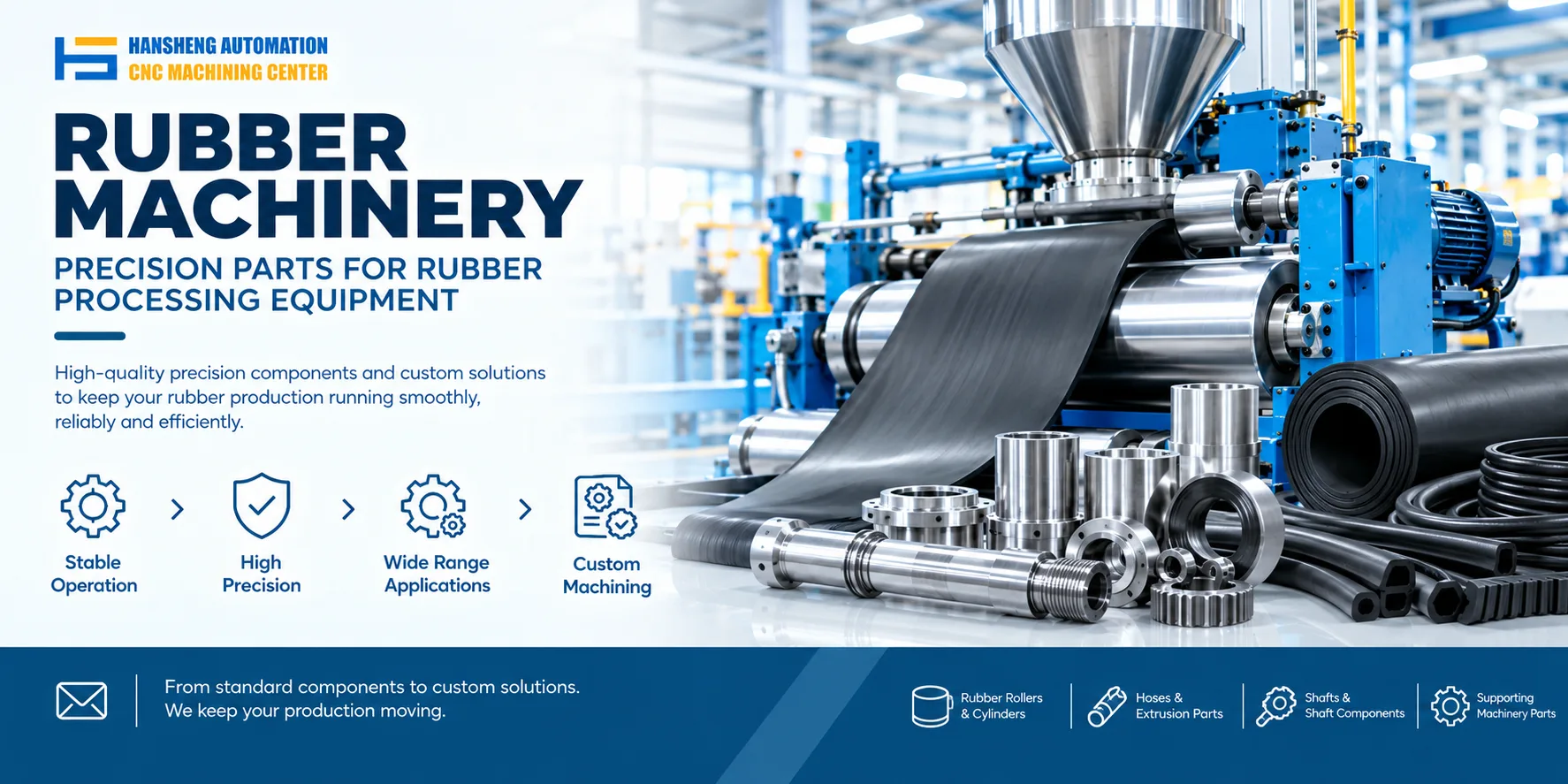
Manufacturing a calender machine frame involves structural design, material preparation, component machining, assembly, alignment, and performance testing. The main requirements are sufficient load bearing strength and accurate component positioning to ensure stable machine operation under working loads.
Structural design and planning
First, determine the calender type and its functional requirements, then develop a three dimensional model of the frame structure. Calculate the frame's load bearing capacity, taking into account roll pressure and motor vibration loads. The design must also define the installation positions of individual components, including the control cabinet base and the mounting holes reserved for the calender assembly.
For example, a conductor calendering machine requires shaft bearing locations at the top of the main support frame. The shaft axis deviation must be controlled within ±0.05 mm.
Material selection and preparation
Select suitable materials according to the structural load requirements. Common options include Q345B low alloy steel and HT250 cast iron.
The plate thickness is generally 20 mm or greater. The columns commonly use H section steel with dimensions of 300 × 300 × 10 × 15.
Before machining, check the material's mechanical property report. The specified yield strength must be at least 345 MPa.
Component machining and welding
Use CNC plasma cutting to prepare the steel components. For welded joints, control the groove geometry carefully. The specified V groove angle is 60° ±5°.
Weld the main support structure using CO₂ gas shielded welding. Maintain the interpass temperature at 150°C or below to meet the specified welding requirements.
The shaft mounting holes require precision boring, with the hole diameter tolerance controlled to H7. Accurate machining of these mounting locations is necessary to achieve the required alignment during assembly.
Assembly and alignment
Assemble the frame from the bottom upward and from the inside outward. First, secure the base and level it to a horizontal tolerance of ≤0.1 mm/m. Install the columns and crossbeams in sequence.
Use a laser tracker to measure the coaxiality deviation of the bearing housings. If the deviation exceeds 0.1 mm, readjust the positioning and locating pins until the required alignment is achieved.
Quality inspection and verification
Inspect the welds using magnetic particle testing to check for cracks. Perform a static load test on the load bearing joints at 1.25 times the specified load.
The frame should then undergo a 72 hour simulated operating test. During the test, monitor vibration amplitude and temperature changes. The specified vibration amplitude is ≤50 μm, and the temperature difference at the bearing locations must remain ≤15°C.
These checks help verify the structural condition and operating stability of the assembled frame against the specified requirements.
Commissioning and final adjustments
During the no load test, measure the radial runout of the main drive system. During the load test, gradually increase the rolling force to 120% of the design value.
Observe the frame's elastic deformation under load. The typical allowable deformation is ≤0.5 mm/m. If the measured result falls outside the specified range, the frame structure and assembly alignment require further evaluation.
Custom precision machining for calendering equipment
Hansheng Automation provides custom precision machining for nonstandard mechanical components based on customer supplied drawings. For calendering equipment and related industrial machinery, we manufacture parts according to the specified dimensions, tolerances, and structural requirements to support component replacement, equipment maintenance, and custom manufacturing projects.
Our precision machining services also cover components for tobacco packaging machinery and filling equipment, along with structural parts for yachts and remote control racing cars. Each component is machined according to the customer's drawings and application requirements.