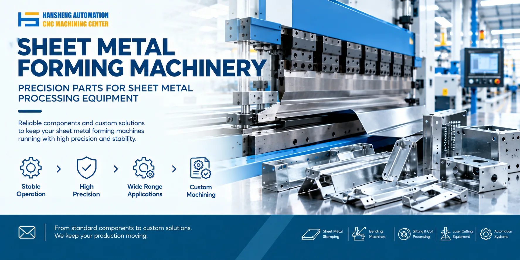
An electro-hydraulic servo press brake uses an electrical control system and hydraulic power to control ram movement during sheet metal bending. The CNC controller processes the bending commands, while the hydraulic system supplies the force required to move the ram and form the workpiece.
Understanding the working principle helps operators identify common problems involving machine axes, servo motors, hydraulic cylinders, valves, and electrical controls.
How an electro-hydraulic servo press brake works
The role of the electro-hydraulic servo valve
An electro-hydraulic servo valve converts an electrical control signal into a corresponding hydraulic output. It acts as both an electro-hydraulic conversion component and a hydraulic power amplification stage.
The valve regulates hydraulic flow and pressure according to the control signal, allowing the system to control the movement of hydraulic actuators such as cylinders. This supports precise control of ram position, movement speed, and applied force.
Main components of the servo valve
An electro-hydraulic servo valve typically contains three functional sections:
Electromechanical converter: Converts the electrical input signal into mechanical displacement or force.
Hydraulic amplifier: Uses this mechanical movement to regulate hydraulic fluid flow and pressure.
Feedback mechanism: Provides feedback within the valve or associated control system, depending on the design, to help regulate the hydraulic output.
The exact valve structure depends on the servo valve design.
Operating sequence
When the CNC controller issues a bending command, it sends control signals to the hydraulic control system. The servo valve regulates oil flow to the cylinders, causing the ram to move downward and form the sheet metal.
Position sensors, commonly linear scales, measure the ram position and send feedback to the controller. The controller compares the measured position with the commanded position and adjusts the hydraulic control output as needed.
This closed-loop control process helps maintain ram synchronization and bending consistency. The final bend angle also depends on the material properties, tooling, machine deflection, and springback compensation.
Common questions about CNC press brakes
How many axes does a CNC press brake have?
The number of controlled axes depends on the machine configuration. Some advanced CNC press brakes offer more than 18 controlled axes when additional positioning systems and auxiliary equipment are included.
Commonly controlled axes include:
| Axis | Function |
|---|---|
| Y1 and Y2 | Control the vertical movement of the left and right sides of the ram |
| X | Moves the backgauge forward and backward to set the flange dimension |
| R | Moves the backgauge vertically |
| Z1 and Z2 | Move the backgauge fingers laterally |
| W or V | Controls worktable crowning compensation, depending on the machine's naming convention |
Additional controlled movements may include independent backgauge positioning, auxiliary sheet support, front positioning systems, and other mechanisms used to handle different workpiece geometries.
Not every press brake includes all these axes. The available functions and axis designations depend on the CNC controller and machine configuration.
What does the servo motor beside the hydraulic valve block do?
The function depends on the machine's hydraulic system design.
In a servo-pump or hybrid hydraulic system, the servo motor drives the hydraulic pump and adjusts its output to match the required flow and pressure. This helps control hydraulic power delivery and can reduce energy losses when full pump output is unnecessary.
A separate servo motor may drive the backgauge. In that case, it controls the positioning distance through an axis such as X or R.
These functions should not be confused. The hydraulic system provides the force required for bending, while the backgauge positioning system determines where the sheet is positioned relative to the tooling.
How are the hydraulic cylinders controlled?
The hydraulic cylinders are controlled through the hydraulic valve assembly and the machine's control system.
On conventional torsion-bar press brakes, ram synchronization is generally mechanical. Depending on the machine design, the stroke or stopping position may be controlled through mechanical stops or screw adjustment mechanisms.
On electro-hydraulic servo press brakes, linear scales provide position feedback to the CNC controller. The controller regulates the hydraulic valves to coordinate the Y1 and Y2 axes and control the ram position.
The precise control method depends on the press brake's mechanical structure, hydraulic circuit, and CNC system.
Why does a hydraulic press brake cylinder fail to move?
A hydraulic cylinder that does not move may have a hydraulic, mechanical, or electrical fault. The following checks can help identify the cause.
Hydraulic system: Check the hydraulic oil level, pump operation, system pressure, and valve condition. Inspect the solenoid valve for electrical faults or a stuck spool, and check whether the relief valve is operating correctly.
Cylinder condition: If the cylinder moves downward unexpectedly while the machine is not commanded to move, inspect for possible internal leakage or faults in the hydraulic control circuit.
Electrical controls: Check whether the solenoid valve receives the required control signal. Inspect the relevant intermediate relays, wiring, fuses, and controller alarm records according to the machine's electrical diagram.
Hydraulic faults require further diagnosis if the initial checks do not identify the cause. Work on electrical components or pressurized hydraulic circuits should be carried out by qualified personnel using the manufacturer's service procedures.
Custom precision machining for industrial equipment
Hansheng Automation provides custom precision machining based on customer drawings for a range of industrial applications. Our work includes components for yacht equipment and RC racing cars, along with nonstandard parts for tobacco packaging machinery and filling machinery. Each component is manufactured according to the supplied drawings and the specific dimensional and structural requirements.