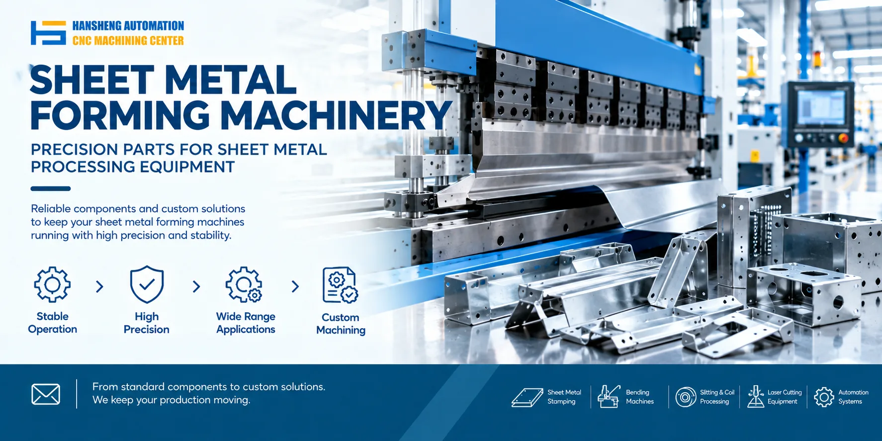
Correct startup and tooling setup help maintain bending accuracy and prevent damage to the machine, dies, and workpieces. Before starting a CNC press brake, check the lubrication system, tooling condition, backgauge alignment, and drive belt tension. Follow the machine manufacturer's operating instructions throughout setup and production.
Pre-Startup Checks
Lubricate the guideways and moving components
Check the lubrication condition of the guideways, backgauge, and other moving components connected to the centralized lubrication system. Confirm that the lubrication supply is functioning correctly and that the required maintenance intervals have been followed.
Inspect the tooling
Check the punch and lower die for contamination, cracks, excessive wear, or other damage. Damaged tooling can affect bending accuracy and may cause further damage during operation. Replace or repair tooling when necessary, following the manufacturer's requirements.
Check backgauge alignment and drive belt tension
Verify that the backgauge is parallel to the required reference and that its drive belt has the correct tension. Incorrect alignment or belt tension can affect positioning accuracy and repeatability.
Startup Procedure
Connect the power and switch on the machine
Connect the machine to its designated power supply and turn on the main power switch according to the startup procedure. Check the control panel for alarms before proceeding.
Start the hydraulic pump
Press the hydraulic pump start button. Listen for unusual noises and confirm that the pump operates normally. The machine should remain in its standby state until a movement command is issued through the control system.
Operate the machine according to the prescribed procedure
Follow the operating manual and the training instructions for the specific CNC press brake. Confirm that the selected operating mode, tooling setup, and programmed parameters are appropriate before starting a bending cycle.
Monitor machine operation
Watch for abnormal sounds, vibration, unexpected movement, or other signs of malfunction during operation. Stop the machine if an abnormal condition occurs, and investigate the cause before restarting. Use the troubleshooting procedures provided in the machine's training or operating manual.
Respond correctly to alarms
If the machine stops because of an alarm, identify the alarm code and its cause before taking further action. Do not repeatedly restart the machine or bypass an alarm without understanding the fault. Follow the manufacturer's troubleshooting procedure to avoid equipment damage and safety risks.
Inspect the first workpiece
When running a new program or changing the setup, inspect the first workpiece against the drawing. Check the required dimensions, bend angles, and overall shape before continuing with the production batch.
Check the tooling during production
Monitor the punch and lower die throughout the bending process. If the tooling becomes loose or shows signs of damage, stop the machine and inspect the setup before resuming production.
Tooling and Machine Adjustments
Adjust the ram stroke
Set the ram stroke before bending to prevent the upper punch from moving too far and damaging the tooling or machine.
The original setup guidance specifies a clearance equal to one sheet thickness when the upper punch reaches the lowest position. This should be treated as a machine specific reference rather than a universal setting. The actual stroke and clearance must be established according to the machine design, tooling geometry, material thickness, and bending requirements.
Where supported, electric stroke adjustment can simplify setup and reduce adjustment time.
Select the lower die V-opening
Choose the lower die V-opening according to the sheet thickness and material properties. A common starting guideline for air bending is a V-opening approximately eight times the material thickness.
For example, when bending 4 mm sheet metal, an opening of approximately 32 mm may be used as an initial reference. The final selection depends on the material grade, required bend radius, flange dimensions, tooling limits, and available machine tonnage.
Adjust the backgauge
Use the CNC control system for rapid positioning and manual fine adjustment where the machine supports both functions. Check the backgauge position and alignment before bending to help maintain the required dimensions.
If positioning errors occur, inspect the reference settings, mechanical alignment, and drive system before changing the programmed dimensions.
Operate the foot switch correctly
Use the foot switch according to the machine's specified operating mode. Its response when pressed or released depends on the CNC control system and safety configuration.
Do not assume that releasing and pressing the pedal will always stop and resume ram movement in the same way across different machines. Confirm the pedal logic in the operating manual and keep hands clear of the punch and die hazard zone throughout the bending cycle.
Operating and Maintenance Precautions
Follow the safety procedures. Operators must understand the machine controls, tooling arrangement, and applicable safety requirements before operating the press brake.
Maintain the machine regularly. Keep the machine clean, check lubrication, and inspect the hydraulic system, guideways, tooling, and backgauge drive components according to the maintenance schedule.
Provide appropriate operator training. Operators should be trained in startup procedures, program selection, tooling installation, alarm handling, and safe workpiece positioning.
Record production data. Keep records of bending parameters, tooling changes, inspection results, and recurring faults. These records help identify setup problems and improve process consistency.
Custom Precision Machining for Industrial Equipment
Hansheng Automation provides custom precision machining based on customer drawings for a range of industrial applications. Our work includes precision components for yacht equipment and RC racing cars, as well as nonstandard parts for tobacco packaging machinery and filling machinery. Each component is manufactured according to the supplied drawings and the specific dimensional and structural requirements.