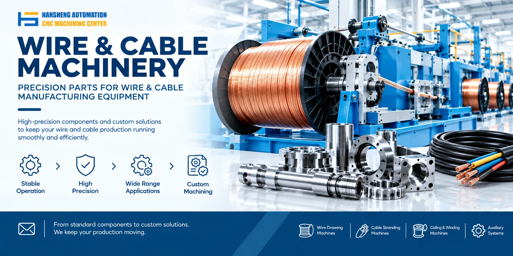
The take-up process on a cable strander can be divided into five steps: traverse preparation, wire feeding, take-up start, traversing, and take-up completion. The goal is stable spool mounting, uniform tension, and matched speed. Hansheng Automation provides build-to-print custom machining for take-up assemblies. We make guide wheels, traverse rods, drive shafts, flanges, and mounting bases from customer drawings.
1. Traverse preparation
When installing the take-up spool, confirm that it is secure and will not shift during rotation. For precision cables such as optical fiber and multi-core shielded wire, set the traverse pitch manually or through the CNC system. A common range is 0.5 to 3 mm to avoid layer overlap. In automotive wire harness production, for example, traverse error is often required to stay within ±0.2 mm.
2. Wire feeding
The wire passes through a guide wheel set, usually 3 to 5 wheels, and forms an S-shaped path so the tension sensor can monitor it effectively. Tension should stay at 10% to 15% of the stranded wire's tensile strength. For a 1.5 mm² wire, the setting is often 15 to 20 N. The friction coefficient between the cable surface coating, such as PVC or TPU, and the guide wheel material also needs to match.
3. Take-up start
Modern machines mostly use PLC control. The ratio between take-up speed and stranding speed is generally 1:1.02 to compensate for cable retraction. When the system detects a 10% increase in spool diameter, it automatically reduces the take-up motor speed by 5% to 8% to keep linear speed constant. Some models also have automatic stop on wire break, with a response time of no more than 0.3 seconds.
4. Traversing
The traverse rod is driven by a servo motor, and travel accuracy can reach ±0.1 mm. For cables with large diameter differences, such as 8 mm power cable and 0.3 mm signal wire, the program presets several traverse modes. When traverse misalignment stays within 2% during production, the infrared correction system fixes it within 2 traverse cycles.
5. Take-up completion
Full spool detection is usually triggered by a weight or diameter sensor. A common spool load limit is 500 to 2000 kg. After cutting the cable, use a dedicated fixture to secure the tail end. Aluminum alloy spools need a anti-loosening clip. The take-up record should include wire length, wire diameter deviation within ±0.02 mm, and take-up time.
Our precision custom machining capability is not limited to take-up systems for stranders. Hansheng Automation can machine non-standard metal parts for medical devices, printing machinery, and food machinery from customer drawings. We can also machine yacht components and RC car components, along with specialized parts for tobacco packaging and filling machinery. We focus on build-to-print custom machining and produce single pieces or small batches according to customer drawings. We do not sell complete machines.