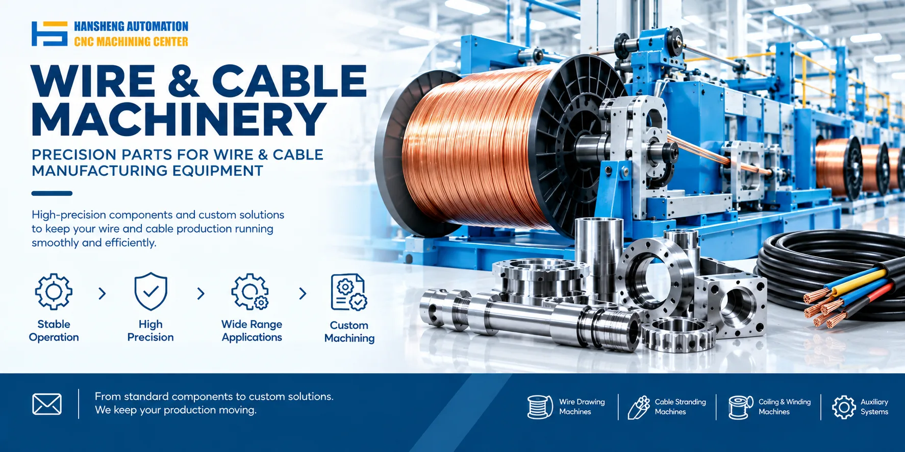
The processing steps for wire-handling equipment depend on the machine type and the parts involved. A stator wire-spreading machine organizes and expands the lead wires after stator winding, while components for a sewing machine thread-pulling device may include structural parts, transmission components, and mounting fittings. These applications have different process requirements. The following sections explain the operating sequence of a stator wire-spreading machine and the machining workflow for components used in sewing machine thread-pulling devices.
1. How does a stator wire-spreading machine work?
A stator wire-spreading machine organizes the lead wires inside a motor stator after winding. The purpose is to keep the wires in the required position and reduce interference during subsequent assembly of the stator and rotor.
Step 1: Stator loading
The operator places the wound stator onto the transfer mechanism at the designated loading position. The transfer mechanism rotates on the worktable, moving the stator between the required processing stations.
Step 2: Positioning and clamping
When the stator reaches the designated station, a positioning mechanism lifts or supports it from below. This keeps the workpiece in the correct position during processing and reduces the risk of displacement.
Step 3: Spreading the lead wires
Several wire-spreading mechanisms are arranged at regular intervals around the transfer mechanism. These mechanisms move vertically to expand the lead wires inside the stator in the required direction.
The spreading action creates more clearance for subsequent assembly and helps prevent the wires from interfering with the fit between the stator and rotor. The mechanism layout and movement parameters depend on the stator design, winding arrangement, and assembly requirements.
Step 4: Unloading and inspection
After the wire-spreading operation is complete, the operator or an automatic unloading mechanism removes the stator from the fixture and transfers it to the next production stage.
The wires should be checked to confirm that they are properly spread and show no obvious displacement, pinching, or damage.
2. What are the machining steps for sewing machine thread-pulling components?
The structure, mounting positions, and transmission arrangements of a sewing machine thread-pulling device determine the design and machining requirements of its components.
For replacement parts and custom components, we can review customer drawings, material specifications, and operating requirements before selecting a suitable manufacturing process. The typical workflow includes the following steps.
Step 1: Drawing review and process planning
Before machining begins, the engineering team reviews the component drawings to identify overall dimensions, critical tolerances, hole positions, mating surfaces, and surface finish requirements.
For irregular parts or components that must fit existing equipment, the review should also consider machining datums, fixture access, and assembly relationships. This helps determine a practical process sequence and reduces the risk of dimensional problems during assembly.
Step 2: Material selection and blank preparation
The material is selected according to the component's load requirements, operating environment, and design specifications. Common options include carbon steel, stainless steel, and aluminum alloys. Some components may also be machined from cast blanks.
Before machining, the blank should be checked for material conformity, surface condition, and machining allowance. Visible corrosion, deformation, or other defects should be assessed and addressed where necessary.
Heat treatment, such as annealing, may be required depending on the material condition and component requirements. It is not necessary for every part.
Step 3: Workholding and datum alignment
The appropriate fixture depends on the component's shape, dimensions, and machining requirements. Thin walled parts, irregular components, and parts with limited clamping space may require dedicated fixtures to reduce vibration and deformation during machining.
After clamping, the workpiece position must be checked against the selected machining datums. For components with tight positional tolerances, consistent datum selection and accurate repositioning are particularly important.
Step 4: Tool selection and machining parameter setup
Cutting tools and machining parameters should match the material, geometry, and required accuracy. Steel and aluminum components, for example, generally require different cutting conditions. Deep holes, threaded features, narrow slots, and complex surfaces may also need different machining methods.
Rough machining removes excess material while leaving sufficient stock for finishing. Finishing operations focus on dimensional accuracy, geometric tolerances, and surface quality. For components with several machined faces, the process sequence should minimize cumulative errors caused by repeated clamping.
Step 5: Machining and process coordination
Depending on the drawing requirements, the component may undergo CNC turning, CNC milling, drilling, tapping, grinding, or wire EDM. Each process produces particular geometric features, so the operations must be arranged according to the component's structure and tolerance requirements.
For shaft components, the main concerns may include outside diameter, concentricity, and mating dimensions. For brackets, the important features may include mounting hole positions, datum surface flatness, and the relative positions of multiple machined faces.
Components with tighter tolerances may require additional setups, finishing operations, or dedicated precision correction processes, depending on their design.
Step 6: Dimensional inspection and surface finishing
After machining, suitable measuring instruments are used to check critical dimensions and geometric tolerances. These may include calipers, micrometers, height gauges, and coordinate measuring machines.
The inspection plan should follow the drawing requirements. Visual inspection alone cannot establish whether a component meets its specified tolerances.
If the drawing calls for deburring, sandblasting, anodizing, electroplating, or another surface treatment, the process should be selected according to the material and intended operating environment. Critical dimensions may need to be rechecked after surface treatment to confirm that the finished component still meets its fit requirements.
Step 7: Final inspection and packaging
Before delivery, the finished components are cleaned to remove chips, oil, and other residues. The supplier then checks the required dimensions, quantity, and visible condition.
Packaging should meet the customer's requirements for corrosion protection and impact resistance during storage and transportation.
For custom machined components, the drawing revision, material specification, and inspection records should correspond to the actual production order. This makes future repeat orders easier to manage and supports quality traceability.
3. What should you consider when customizing components for wire-handling equipment?
The main machining challenges depend on the component's geometry, assembly relationships, and operating conditions. When replacing an existing part or developing a custom component, several points deserve attention.
Dimensions and fits: Check mounting hole spacing, shaft and bore fits, datum surfaces, and interfaces with adjacent components.
Material and machining process: Select the material and manufacturing method according to load, wear resistance, corrosion resistance, and operating conditions rather than pursuing unnecessarily tight tolerances.
Tolerances and inspection: Specify the required tolerances for dimensions that affect installation or motion, then inspect those features after machining.
Manufacturing feasibility: For irregular shapes, special hole patterns, or complex mounting surfaces, evaluate tool access, workholding, and machining sequence before production.
Customers who need replacement parts, brackets, shafts, connecting components, or other custom mechanical parts for wire-handling equipment can provide drawings, sample dimensions, and material requirements. We can assess the component structure and specified tolerances, then arrange single piece prototyping or small batch production according to the order requirements.
Hansheng Automation also provides custom precision machining for components used in other industries. Our work includes parts for yacht equipment, RC racing cars, tobacco machinery, and filling and packaging machinery. We manufacture these non-standard mechanical components according to customer drawings and specified technical requirements, with the process selected to suit each part's material, geometry, and intended application.