A swirl-vane spray tower, also known as a swirl-plate tower or vane-type cyclonic scrubber, is a wet gas treatment device used to remove particulate matter, liquid droplets, and other contaminants from industrial exhaust.
Its internal structure uses fixed swirl vanes to change the direction of the rising gas stream and generate centrifugal motion. Scrubbing liquid is distributed across the vanes, forming liquid films that interact with the swirling gas. The resulting droplets capture suspended particles and move toward the tower walls under centrifugal force.
Swirl-vane spray towers are used in industrial dust and mist control applications. Their performance depends on gas velocity, liquid distribution, particle characteristics, and tower configuration.
Working Principle of a Swirl-Vane Spray Tower
The design of a swirl-vane spray tower is based on the arrangement of fixed blades, which resemble the blades of a fan or windmill.
When the exhaust gas passes through the swirl vanes, its flow direction changes and a rotating motion develops. This increases the relative movement between the gas, liquid film, and suspended particles.
The liquid is distributed from the central blind plate toward the individual vanes, forming thin liquid films along their surfaces. As the gas flows upward through the vanes, the liquid films are disturbed and broken into smaller droplets.
Centrifugal force moves the droplets, together with the particles they capture, toward the tower walls. The liquid then flows downward under gravity and collects in the liquid collection section. Through an overflow arrangement, part of the liquid can flow into the blind-plate section of the next tray.
This repeated gas-liquid contact improves particle collection and liquid separation. A mist eliminator can be installed downstream to capture droplets that remain entrained in the exhaust.
Swirl-vane towers are particularly useful for applications involving dust and liquid mist. However, collection efficiency varies with particle diameter, gas velocity, droplet size, and the internal structure of the tower. A single removal efficiency value cannot represent all operating conditions.
Design Considerations
Designing a swirl-vane spray tower involves gas flow, liquid distribution, centrifugal separation, pressure loss, and particle movement. The appropriate parameters depend on the exhaust characteristics and equipment geometry.
Pressure Drop
Pressure drop generally increases as the inlet gas velocity rises. For a given equipment geometry and operating condition, the pressure loss is commonly related to the square of gas velocity, although the actual relationship also depends on blade geometry, liquid flow rate, and other design factors.
Higher gas velocities can improve the relative movement between particles and liquid droplets, but they also increase airflow resistance and fan power requirements.
The pressure drop should therefore be considered together with the required collection efficiency and available fan capacity.
Erosion and Wear
When the exhaust contains abrasive particles, high gas velocities can increase wear on the swirl vanes and tower walls.
The actual erosion rate depends on particle hardness, size, concentration, impact angle, gas velocity, and construction material. It should not be assumed to follow a fixed cubic relationship with inlet velocity under all conditions.
For abrasive dust applications, the tower may require thicker metal sections or suitable wear-resistant protection. Regular inspection of the vanes, inner walls, and liquid collection areas is also necessary.
Particle Characteristics
Particle properties affect separation performance.
Brittle particles or weakly agglomerated dust may break into smaller particles under high-impact or high-shear conditions. Smaller particles are generally more difficult to collect through centrifugal separation.
High gas velocities can also cause liquid droplets collected on the tower walls to become re-entrained in the gas stream. The operating velocity must therefore be selected to balance separation performance, pressure drop, and liquid carryover.
Preliminary Design Parameters
The reference design description provides the following preliminary values:
Inlet gas velocity: 14-24 m/s.
L/D ratio: 3-6, where L represents the relevant tower length and D represents its diameter.
Tower diameter: Not more than 900 mm per tower.
These values should be treated as reference parameters for the described equipment configuration, not universal design standards. Actual dimensions and operating conditions must be verified through gas-flow calculations and equipment-specific testing.
Where a single tower cannot provide the required treatment capacity, multiple towers can be connected in parallel to handle larger exhaust volumes.
Material Selection
Common construction materials include stainless steel, carbon steel, and polypropylene (PP).
For applications involving abrasive particles, metal construction may be preferred because of its mechanical strength. Thicker steel sections or wear-resistant internal protection can help reduce damage caused by particle impact.
For corrosive exhaust streams, material selection must also account for chemical compatibility, gas temperature, and liquid composition. PP or suitable corrosion-resistant metal materials may be considered according to the operating environment.
Main Features of Swirl-Vane Spray Towers
Centrifugal Particle and Droplet Separation
The swirling gas flow creates centrifugal force that moves suspended particles and liquid droplets toward the tower walls. This allows the equipment to perform dust collection and droplet separation in the same treatment chamber.
For cyclonic spray scrubbers, the US EPA reports collection efficiencies as high as 95% for particles larger than 5 μm, while reported collection efficiencies for submicron particles range from 60% to 75%. These figures are reference values for cyclonic spray scrubbers, not guaranteed performance figures for every swirl-vane tower.
Reduced Risk of Packing Blockage
Compared with some densely packed scrubbers, the open vane structure provides relatively unobstructed gas passages. This can reduce the risk of blockage when treating exhaust containing suspended solids or paint mist.
However, deposits may still accumulate on the vanes, tower walls, and spray nozzles. Regular cleaning and inspection remain necessary, particularly when the exhaust contains sticky or adhesive contaminants.
Operation at Relatively High Gas Velocities
The centrifugal effect allows swirl-vane towers to operate at relatively high gas velocities while maintaining effective particle and droplet separation within their design range.
Higher gas velocity can reduce the equipment cross-sectional area required for a given airflow rate. However, excessive velocity may increase pressure drop and liquid re-entrainment, reducing overall separation performance.
Equipment Cost and Maintenance
The internal vane assembly, liquid distribution system, and related manufacturing requirements make swirl-vane towers more complex than simple spray chambers.
Their manufacturing costs can therefore be higher than those of basic spray towers. Actual investment and maintenance costs depend on tower dimensions, materials, internal structures, and operating conditions.
Features of the Renxinyuan Swirl-Vane Spray Tower
The Renxinyuan swirl-vane spray tower described in the original equipment design uses a two-stage structure consisting of a cyclone separation section and a spray treatment section.
Cyclone Separation Section
The cyclone section uses multiple cyclone tubes arranged in parallel to increase the total exhaust gas handling capacity.
This arrangement allows the system to distribute the gas flow among several separation channels. It also helps reduce the footprint and overall height compared with a configuration using a single large cyclone chamber.
As the exhaust passes through the cyclone section, centrifugal force separates a substantial portion of the larger dust particles from the gas stream. The collected particles move toward the cyclone walls and are discharged into the collection section.
Spray Treatment Section
After cyclone separation, the exhaust enters the spray section, which includes packing material to increase the available gas-liquid contact area.
The scrubbing liquid flows over the packing while the gas passes through the section. This provides additional contact between the liquid and residual suspended particles, allowing further dust and mist removal.
A mist eliminator is installed downstream to separate entrained liquid droplets before the treated gas leaves the tower.
This two-stage arrangement combines centrifugal pre-separation with the gas-liquid contact provided by packed sections. The cyclone stage removes a portion of the incoming dust load, while the spray section provides additional treatment.
Compared with a packed tower operating alone, the upstream cyclone section can reduce the amount of particulate matter entering the packing and help limit blockage.
The design is intended for applications involving dust and mist, particularly paint mist that may accumulate on conventional packing. However, fine-particle removal and long-term resistance to fouling still depend on the operating conditions, packing design, liquid circulation, and maintenance frequency.
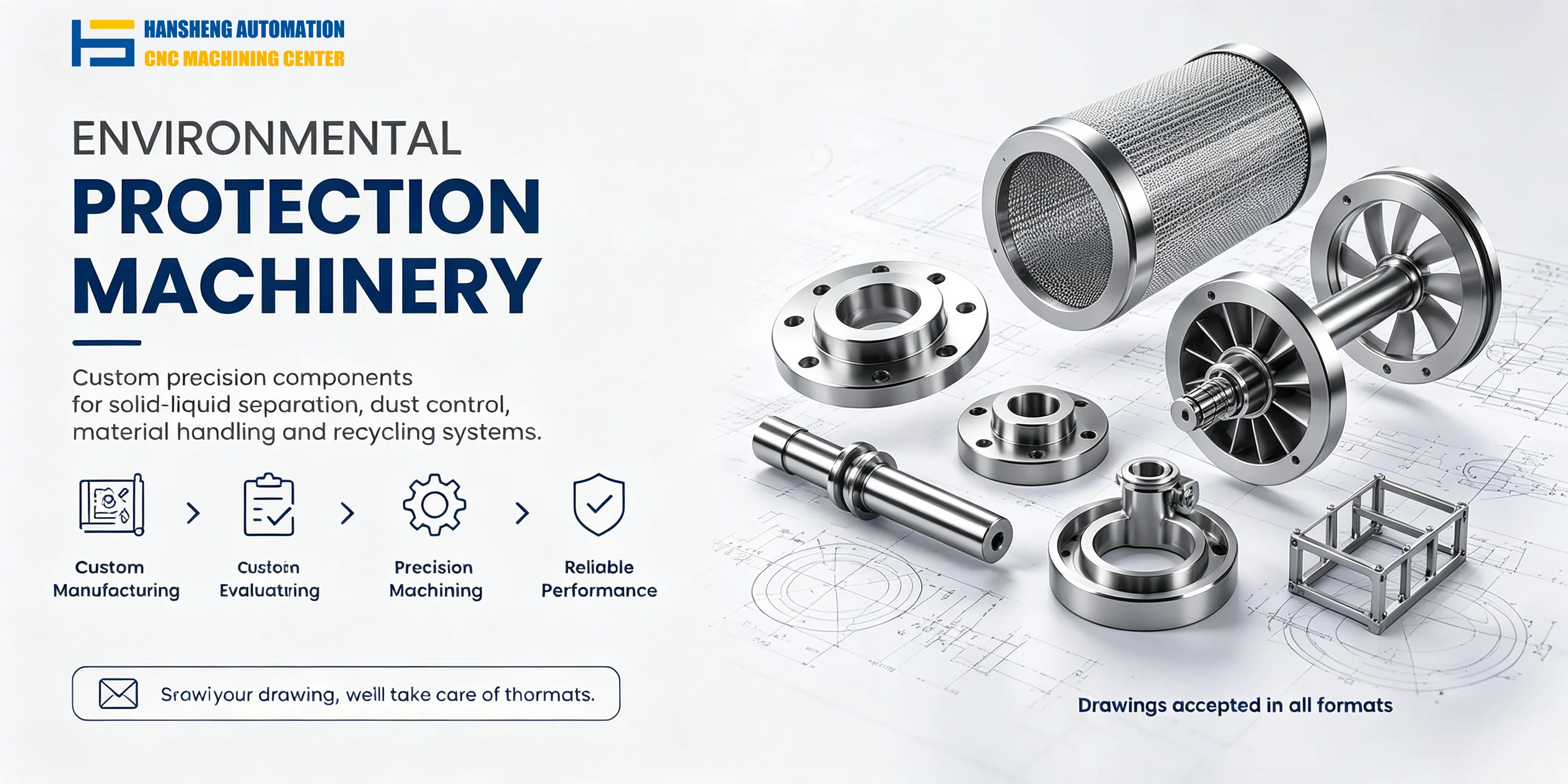
Custom Machining for Industrial Equipment Components
In addition to components used in environmental protection and dust treatment equipment, Hansheng Automation provides drawing-based precision machining for non-standard industrial parts.
Our machining services also cover precision components for yacht equipment, remote-controlled racing cars, tobacco and packaging machinery, and filling equipment. We support single-piece and small-batch manufacturing according to customer drawings, dimensions, and machining requirements.