The core principle of a multi-station rotary machine lies in the coordinated cycle of power drive and precision positioning.
1. Power Drive System
An electric motor serves as the power source, transmitting power through belts, chains, or gears to drive the rotary table in circular motion. For example, in electronic component assembly equipment, a stepper motor finely adjusts speed and rotation angle to ensure smooth movement of workpieces.
2. Station Layout Strategy
Stations on the rotary table are arranged according to the process sequence. For instance, in a cosmetic filling machine, the first station places empty bottles, the second station fills liquid, the third station seals the bottle, and the final station applies labels. The spacing between stations is fixed, forming a continuous production-line operation.
3. Positioning Device Principle
Mechanical positioning uses locating pins or cams to lock the rotary table position. Electrical positioning relies on photoelectric sensors to detect position signals and feed data back to the control system. In automotive parts inspection machines, proximity sensors can accurately control the rotary table to stop within an error of 0.1 mm.
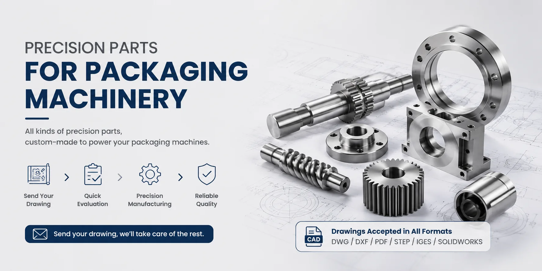
For precision-machined rotary tables, cam indexers, locating pins, or other custom components used in multi-station rotary machines, Hansheng Automation provides machining services based on customer drawings.
4. Working Cycle Flow
Workpieces enter the rotary table from the initial station, and one process operation is completed with each rotation. In a watch assembly machine, the dial is first fixed by a vacuum suction cup, then rotated to the next station for automatic installation of the hands, and further rotated to the movement assembly position for integration. The entire process requires no manual intervention.
5. Control System Architecture
The PLC coordinates all components through program instructions: receiving sensor signals, calculating the rotary table angle, triggering pneumatic actuators for processing, and controlling the unloading robotic arm. For example, in a food packaging line, the system can be set to complete one indexing movement every 3 seconds while simultaneously activating actuators at 12 stations.