During the commissioning and wet-testing of automated liquid filling equipment, process stability and mechanical coordination often encounter technical hurdles. The following corrective actions provide structured solutions to the most frequent commissioning faults:
1. Inaccurate or Inconsistent Dosing
Metering Recalibration: Re-verify and zero the load cells or mass flow meters, tightening measurement deviation within ±0.5%.
Bubble and Entrained Air Elimination: In micro-dosing and viscous filling, foam leads to volumetric errors. Integrate an upstream degassing chamber or extend holding dwell time (recommended ≥30 seconds).
Valve Actuation Timing: Fine-tune pneumatic solenoid valve cut-off timing to 10 ms resolution; verify that supply air pressure remains stable between 0.6 and 0.8 MPa to prevent delayed shut-off.
2. Product Leakage at Joints and Seals
Gasket Selection and Assembly: Replace damaged or swollen seals with PTFE or encapsulated FKM gaskets, applying food-grade silicone grease during assembly to prevent twisting.
Piping Pressure-Decay Verification: Conduct pneumatic hold-testing across the fluid manifold at 0.4 MPa. Pressure loss must not exceed 0.02 MPa over a 5-minute holding period.
Tri-Clamp Preload: Ensure sanitary Tri-Clamp fasteners are evenly torqued to 15–20 N·m in accordance with ASME BPE standards to eliminate micro-gaps under line pulsation.
3. Nozzle Dripping and Stringing
Positive Shut-Off Dynamics: Upgrade to dual-action pneumatic cylinder shut-off valves to ensure a fast, positive closing response (closing time ≤50 ms).
Snuff-Back Calibration: Adjust pump suck-back volume to 3–5 mL with a delay interval of 200–300 ms to retract residual meniscus at the nozzle orifice.
Nozzle Geometry Optimization: Deploy precision-bored, anti-drip nozzles made from 316L stainless steel with internal surface finishes of Ra ≤ 0.8 μm (or PTFE inner liners).
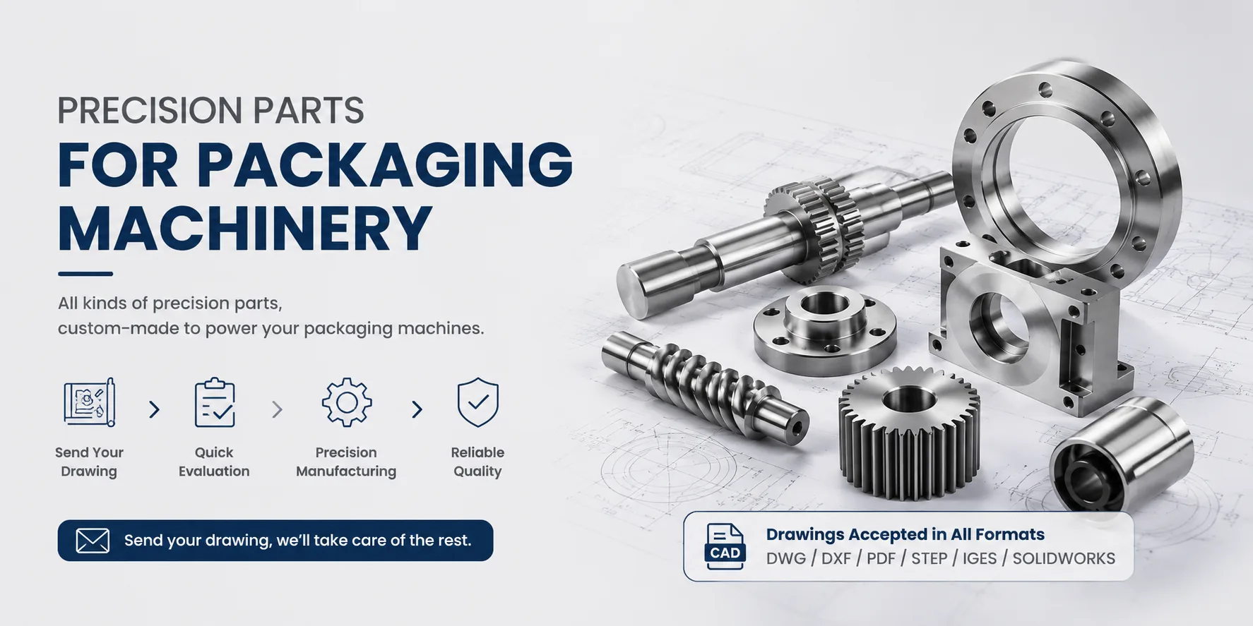
Hansheng Automation manufactures custom sanitary 316L nozzles, valve seats, and anti-drip tips according to client drawings, controlling bore concentricity and edge sharpness to resolve persistent fluid weeping.
4. Unscheduled System Faults and E-Stops
Safety Circuit Diagnostics: Test the safety interlock loop according to IEC 60204-1 standards; verify that safety light curtains and interlock switches deliver a reaction response time under 20 ms.
Overload Tripping: Measure phase current on driving motors against the motor nameplate ratings (380V) to locate thermal or mechanical binding.
PLC Diagnostic Codes: Cross-reference real-time fault logs via the HMI. Codes E01–E05 typically denote sensor misalignment, fiber-optic amplifier saturation, or stroke-limit proximity faults.
5. Conveyor and Transfer Asynchrony
Servo Parameter Tuning: Reconfigure the electronic gear ratio based on the proportional relationship between the motor encoder pulse count and the mechanical drive gear reduction, restoring synchronized linear travel.
Mechanical Drive Alignment: Use a dial indicator to measure the radial runout of conveyor drive rollers and idlers, maintaining runout within ≤0.1 mm.
Timing Belt Tensioning: Adjust tooth belt deflection according to belt pitch profiles, maintaining a midpoint deflection of 3–5 mm under moderate manual load.
We also provide precision CNC machining for custom drive rollers, timing pulleys, and line shaft components to correct mechanical runout and eliminate belt tracking drift.
Safety Advisory: Commissioning involving pressurized tanks, nitrogen blanket circuits, or accumulator vessels must be executed strictly by certified technicians holding pressure-equipment credentials (e.g., TSG Z6001 or equivalent regional standards). Unauthorized servicing of pressure-reducing valves and pressure-retaining components is strictly prohibited.