The structure of an industrial dehydration reactor depends on the material being processed, the dehydration process, and the equipment's intended function. Designs may differ in vessel geometry, heating and condensation arrangements, agitation mechanisms, and material handling systems. The following four examples describe specific reactor designs and their main structural components.
Dehydration reactor for construction waste
Main vessel structure
The vessel consists of an upper section and a lower section joined by a sealed connection. The joint uses either a 20 mm thick stainless steel sealing ring or a 15 mm thick corrosion-resistant alloy sealing ring. The overall vessel can be cylindrical, rectangular, or polyhedral. Polystyrene boards or insulating coatings are applied to the exterior to provide thermal insulation.
Condensation and drainage system
An inverted V-shaped cooling coil assembly is installed inside the upper section. Piping connects the top of the vessel to a heat exchange station, with refrigerant lines connecting both ends of the station to the cooling assembly.
An upward-sloping condensate baffle is mounted on the inner wall of the upper section. A drain line is installed at the connection with the vessel body and fitted with a normally closed solenoid valve. The other end connects to a vacuum water storage tank. An inlet valve, vacuum gauge, and exhaust valve are also installed at the top of the upper section.
Heating and temperature control
The lower section contains multiple electric resistance heating rods or microwave heating plates, together with temperature sensors. The sensors and heating devices connect to a temperature controller, which is linked to the central PLC control system for temperature regulation.
Semipermeable membrane
A hydrophobic, gas-permeable semipermeable membrane is installed between the upper and lower sections. It serves as a functional separator between the two vessel sections in this design.
Dehydration reactor for waterway sediment
Vessel and collection assembly
An annular plate is fixed to the outside of the reactor body. A platform and two support legs are installed on one side of the plate, and a collection tank is placed on the platform. A condenser tube is connected to one side of the collection tank, with one end communicating with the reactor body.
Pressing mechanism
A cylinder is mounted on one side of the vessel and connected to a hydraulic rod. The rod extends into the vessel and is fixed to a pressure plate. A dewatering box is positioned on one side of the plate, forming the pressing assembly.
Agitation mechanism
A motor is mounted on one side of the vessel. Its drive shaft extends into the vessel and is fixed to the dewatering box. Inside the box, a motor-driven shaft carries several fixed stirring rods. Together, these components form the drive and agitation assembly.
Rapid dehydration reactor for polyester polyol
Vessel and vacuum piping
A heating jacket is installed inside the vessel structure. A feed pipe with a control valve passes through one side of the vessel top, while a vacuum line fitted with a vacuum gauge is connected on the other side. An exhaust pipe with a control valve is installed at the end of the vacuum line. The vessel has a length-to-diameter ratio greater than 2.
Drive and agitation assembly
An electric motor is mounted above the vessel, with a gearbox connected beneath it. A shaft extends through the gearbox, and a multifunctional rotary disc is attached to its lower end to form the internal drive and agitation assembly.
Discharge and circulation system
A discharge port is located at the bottom of the vessel and fitted with a discharge valve. A circulation pump connects to one side of the discharge port. A return pipe is connected to the pump, with a distribution opening at the end of the return line. These components form the material circulation path.
Adjustable reactor for oligomeric lactic acid production
Vessel body
The reactor has a cylindrical body with a conical lower section. An insulating outer shell surrounds the vessel. The internal structure includes an agitation mechanism, a scraping mechanism, and an inlet and outlet control assembly.
Scraping mechanism
A rotating ring is mounted at the lower end of the vessel. Its upper end extends into the vessel, while its lower end projects outside. Multiple scraper blades are fixed around the outer portion of the ring's upper face. The projecting end of each scraper blade is connected to a movable plate through a rotary joint.
An electric actuator is fixed to the side of each scraper blade. Its extending end connects through an intermediate rod to a rotary joint at the center of the movable plate.
The mechanism consists of the rotating ring, scraper blades, movable plates, and electric actuators, which work together through rotary connections and linear extension.
Inlet and outlet control assembly
An inlet and outlet control disc is positioned inside the rotating ring and connected to it through a rotary seal. The disc has an inlet on one side and an outlet on the other.
Two vertical slots are located on the upper face of the disc, between the inlet and outlet. A guide plate slides vertically in each slot, with its lower end connected to a second telescopic actuator installed in the slot.
Opening and closing covers are installed above both the inlet and outlet. Each cover is connected to the control disc through a third telescopic actuator and can move vertically. Conveying equipment is connected beneath the control disc.
Adjustable agitator blades
A fixed rod is mounted at the top of the vessel through a sealed rotary connection. An agitator shaft is installed coaxially inside the fixed rod and can both rotate and slide axially.
Multiple connecting shafts are arranged evenly around the lower end of the agitator shaft. Each connecting shaft is perpendicular to the shaft axis. Vertical sliding slots are formed in the corresponding positions at the lower end of the fixed rod.
A connecting block is mounted on each connecting shaft through a rotary joint. An agitator blade is fixed to the outside of each connecting block, and an angle adjustment block is attached to its lower end. Angle adjustment openings are formed in both sides of each sliding slot at the corresponding positions.
An adjustment handwheel is fixed to the upper end of the agitator shaft. A sealed positioning component that engages with the agitator shaft is installed at the top of the fixed rod. A drive gear is fixed to the rod below this component and is driven by an electric motor.
Insulating shell and gas passages
An insulating shell covers the outside of the vessel. Multiple partition plates are arranged around its inner surface, and the spaces between adjacent plates form gas passages.
Vertical distribution chambers are installed at the left and right ends of the shell and connected to the gas passages. Each distribution chamber has a vent opening on its outer side.
Pressure control system
A negative pressure generator and a pressure gauge are mounted at the top of the vessel. The generator controls the pressure inside the vessel, while the gauge displays the pressure.
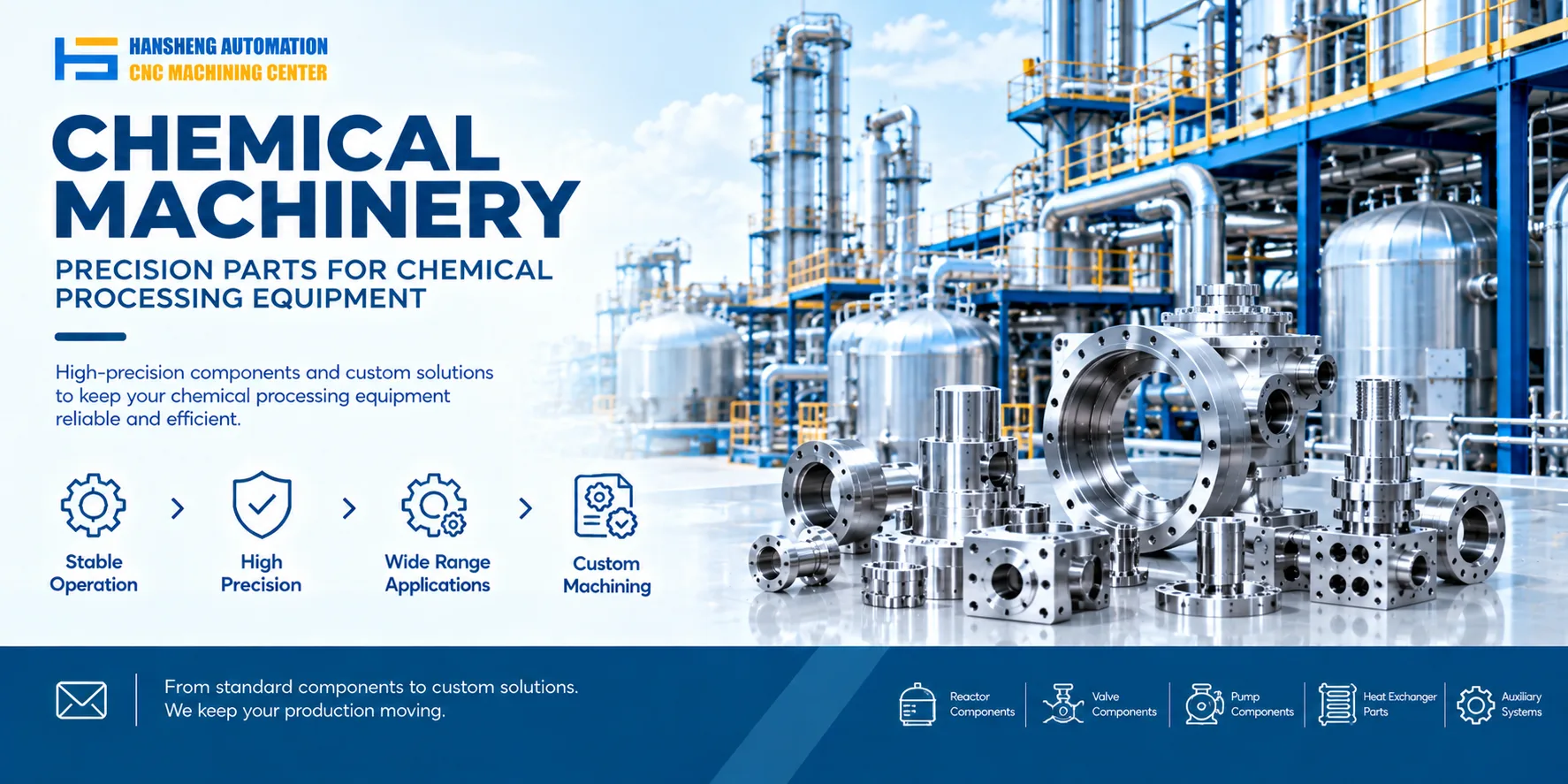
In addition to components for reactor and other industrial equipment, Hansheng Automation provides custom precision machining according to customer drawings. Our work includes parts for tobacco packaging machinery and filling equipment, as well as precision components for yachts and RC racing cars. We manufacture non-standard parts to customer drawings and technical requirements for different equipment applications.