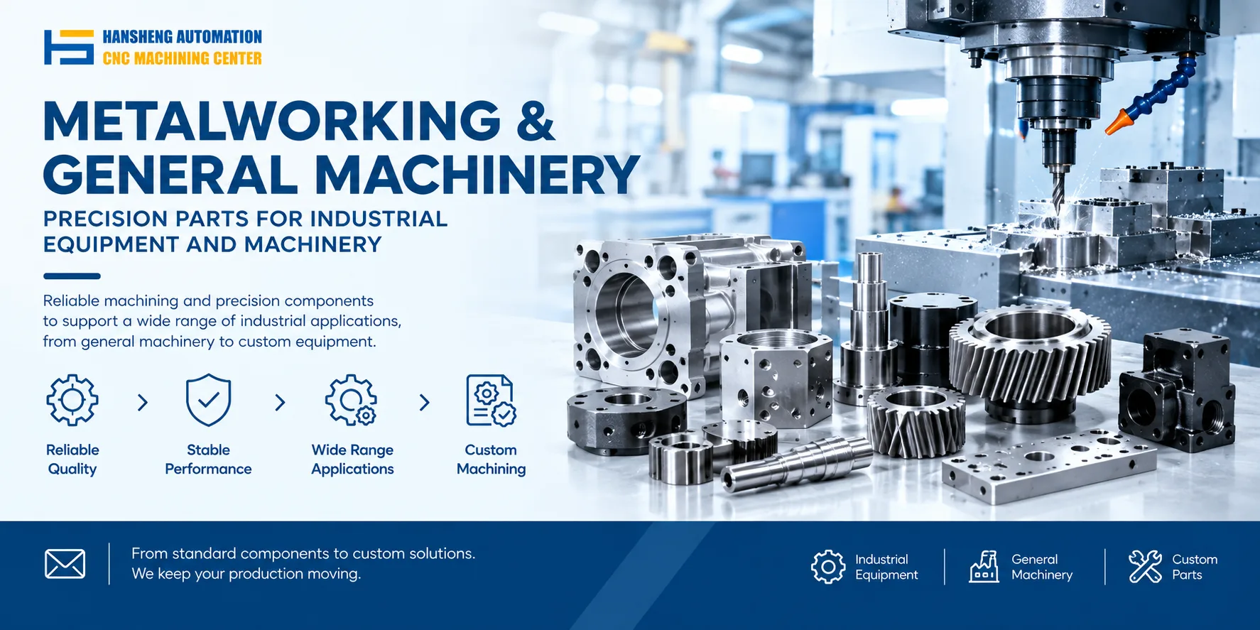
Machining stainless steel pipe fittings on a multi-station machine centers on completing the full process in one clamping. The equipment must suit the high hardness of stainless steel and its tendency to stick to tools. Process control focuses on tool selection, cutting parameters, and clamping accuracy for thin-wall parts.
1. Dedicated equipment configuration
1.1 Main machine
Use a horizontal multi-axis multi-station turret machine or a vertical multi-station rotary table machine. Configure 4 to 8 stations to suit turning and hole machining on pipe fittings.
The spindle should use a high-rigidity hydraulic chuck with a custom expansion sleeve locating mandrel. This prevents thin-wall stainless steel pipe fittings from deforming during clamping.
Integrate automatic tool change. Use TiAlN coated carbide turning tools, cobalt high-speed steel drills and taps, and carbide milling cutters for stainless steel.
We can machine expansion sleeve locating mandrels, hydraulic chuck adapters, tool holders, and fixtures from customer drawings, in single pieces or small batches. Hansheng Automation works to drawing dimensions and assembly clearances.
1.2 Auxiliary systems
Extreme pressure emulsified cutting fluid circulation and filtration system. Flow per line is no less than 20 L/min. High-pressure nozzles aim at the cutting point to reduce stainless steel sticking to tools.
Automatic loading and unloading robot with vibratory bowl magazine for unmanned line operation.
In-line contact probe for size checks between stations and final precision inspection.
2. Standardized machining process
2.1 Pre-processing
Use 304/316L stainless steel seamless pipe. Cut to fixed length by pipe fitting specification. Use a belt sander to deburr the end face. End face perpendicularity must be ≤0.05 mm.
Set tool offset parameters in advance. Keep machining size deviation of each tool within ±0.02 mm.
2.2 Station sequence, taking a 6-station machine as an example
Station 1: Automatic loading. Send the pre-processed pipe fitting to the machining station.
Station 2: Turn the outer diameter and end face. Machine the reference outer diameter and end face flatness. Cutting speed 600 r/min, feed 0.15 mm/r.
Station 3: Drill and ream. Machine the inner bore diameter. Speed 200 r/min, feed 0.08 mm/r. Apply cutting fluid throughout.
Station 4: Tapping. Select the corresponding cobalt high-speed steel tap by thread specification. Speed 100 r/min. Use a floating tapping head to offset coaxiality error.
Station 5: Mill chamfers and seal grooves. Machine the mounting groove and chamfer structure of the pipe fitting.
Station 6: In-line inspection and automatic unloading. The probe checks outer diameter, inner bore, and thread size. Qualified parts go to the unloading bin. Nonconforming parts are rejected to the scrap bin.
2.3 Process control points
Keep cutting speed in the 300 to 800 r/min range. This avoids excessive cutting temperature at high speed that can damage tool coating.
Apply enough cutting fluid during tapping. This reduces tap wear and thread galling risk.
After every 500 parts, check tool wear. Replace tools with wear over 0.1 mm to maintain machining accuracy.
For thin-wall pipe fittings, set chuck clamping force to 5 to 8 bar to avoid clamping deformation.
Our precision parts machining service is not limited to stainless steel pipe fittings. Hansheng Automation can machine custom parts from drawings for automotive parts, hydraulic equipment parts, valve and pump parts, food packaging machinery parts, and medical device parts. We also cover yacht precision fittings, RC car structural parts, and textile machinery parts. Single pieces and small batches are both available, with attention to material, tolerance, surface finish, and assembly fit.