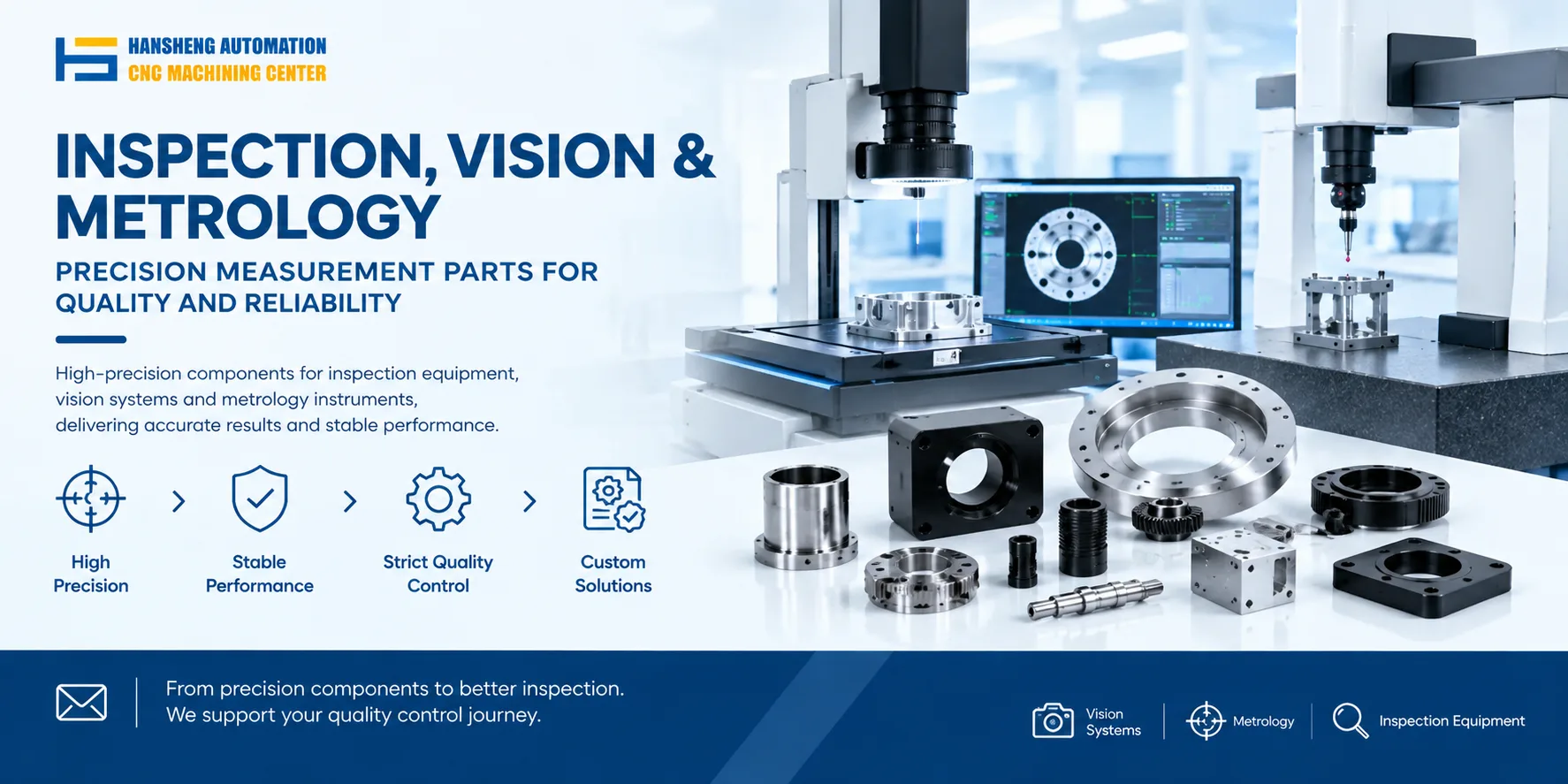
A CCD printing machine consists of six core modules: the visual positioning system, printing execution assembly, substrate carrier mechanism, motion transmission system, rigid machine base, and electrical control system. All components must meet an accuracy level of ±0.01 mm to ensure printing quality.
1. Visual Positioning System (CCD Core Sensing Unit)
1.1 Imaging Components
High-resolution CCD camera, typically 5 megapixels or higher
Telecentric lens to eliminate image distortion and ensure positioning accuracy
1.2 Illumination Components
Ring LED backlight for transparent substrates
Coaxial structured light source for opaque substrates
1.3 Processing Unit
Industrial-grade image processing board for target recognition and coordinate calculation
Positioning algorithm modules such as pixel matching and sub-pixel calculation
2. Printing Execution Assembly
2.1 Printing Head Main Body
Precision squeegee made of stainless steel, with blade straightness within 0.005 mm
Ink storage rubber roller made of nitrile rubber, with wear resistance matched to the printing cycle
2.2 Adjustment Mechanism
Squeegee angle adjustment assembly, adjustable from 0° to 45° to control printing thickness
Rubber roller pressure regulator with servo control, adaptable to different printing media
3. Substrate Carrier Mechanism
3.1 Vacuum Platform
Vacuum adsorption table with uniformly distributed porous openings and stable vacuum level
Anti-static coating to prevent electrostatic damage to the substrate
3.2 Positioning Fixtures
Pneumatic positioning pins for quick locking, with repeat positioning accuracy of ±0.005 mm
Reference positioning blocks aligned with the printing platform datum
4. Motion Transmission System
4.1 Drive Components
X/Y/Z axis servo motors with encoders, accuracy of ±0.001°
Linear guideways and ball screws of ground grade, with reverse clearance within 0.003 mm
4.2 Feedback Components
Linear encoders for real-time position feedback, accuracy of ±0.002 mm
Origin return sensors to ensure startup positioning reference
5. Rigid Machine Base
Cast iron machine body with high rigidity, deformation resistance, and long-term stability
Leveling feet for installation plane calibration, with levelness within 0.02 mm/m
6. Electrical Control System
6.1 Core Controller
PLC for coordinating the actions of all components
Motion control card for executing multi-axis synchronized commands
6.2 Operation Module
Touchscreen HMI for parameter input and printing program recall
Safety interlock devices including emergency stop and door interlocks, compliant with equipment safety standards
For precision-machined components such as positioning fixtures, reference blocks, and custom brackets used in CCD printing machines, Hansheng Automation provides machining services based on customer drawings.