Troubleshooting J2 axis overload in a six-axis robot requires first distinguishing among three root causes: mechanical binding, abnormal electrical parameters, and improper load matching. The problem should be located and resolved step by step, from simple checks to more complex ones.
I. Initial On-Site Troubleshooting
(A) Static Visual Inspection and Manual Testing
Check whether workpieces, cables, or tooling are rubbing against or jamming the area around the J2 axis. Inspect the reducer housing for impact deformation, and check whether lubricating grease is leaking or insufficient.
After cutting off the main power of the robot, manually rotate the arm end of the J2 axis. Feel whether the rotation resistance is uniform, or whether there is sticking, sudden resistance increase, or complete inability to rotate. If the axis cannot rotate at all, check whether the J2 axis electromagnetic brake is stuck or has a coil fault.
(B) No-Load Dynamic Test
Restore robot power and run the J2 axis through its full stroke in reciprocating motion using the teach pendant. Monitor the real-time current of the J2 axis servo motor through the teach pendant or servo monitoring software.
Compare the current value with the no-load current baseline of a normal robot of the same model. If the current exceeds 80% of the rated value or deviates from the baseline by more than 10%, an abnormality exists.
II. Mechanical Fault Troubleshooting and Repair
(A) Transmission System Inspection
Lubrication system check: according to the robot manufacturer's maintenance manual, open the oil filler plug of the J2 axis reducer and confirm that the oil level is within 1/2 to 2/3 of the oil sight glass. If the oil is insufficient, add the specified type of reducer lubricant. If the grease is blackened or contains metal debris, replace all lubricant and disassemble the internal gears for inspection. If the reducer was recently serviced, confirm that the lubricant type and filling amount meet the manufacturer's requirements. Overfilling can increase internal resistance.
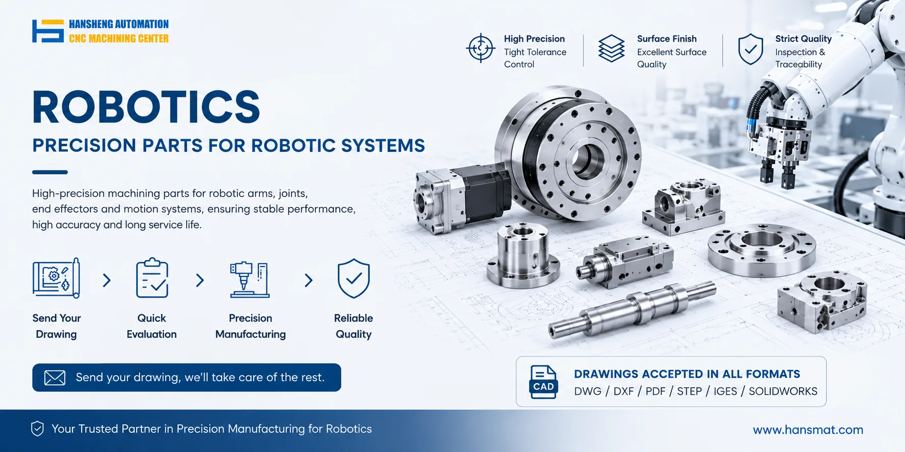
Reducer inspection: most six-axis robots use harmonic reducers or planetary reduction structures for the J2 axis. If manual rotation resistance is abnormal, disassemble the reducer and check the flexspline, circular spline, or planetary gears for broken teeth or wear. Faulty parts must be replaced. For replacement of worn reducer components or related mechanical parts, Hansheng Automation can provide custom machining services based on customer drawings, helping restore proper fit and load capacity.
Synchronous belt tension adjustment: if the J2 axis uses synchronous belt transmission, adjust the tensioner so that the belt deflection at the center is controlled within 5–10 mm when pressed. Both over-tightening and over-loosening increase transmission load.
Load center verification: confirm whether the center of gravity of the fixture and workpiece is close to the center of the J2 axis arm end. If the center of gravity deviates too much, additional torque will be generated and cause overload. In this case, adjust the fixture mounting position.
(B) Rated Load Verification
Check the official robot documentation to confirm the rated load parameters of the J2 axis. Compare the total weight of the current workpiece and tooling. If it exceeds the rated value, replace the tooling with a lightweight version or optimize the operation path.
III. Electrical and Parameter Troubleshooting and Repair
(A) Servo System Hardware Inspection
After disconnecting the main power, check whether the power cable and encoder cable of the J2 axis servo motor are damaged, oxidized, or loose at the connectors. Use a multimeter to measure the insulation resistance of the power cable, which should be greater than 1 MΩ at room temperature. Ensure proper continuity.
Clean dust from the servo drive interface and re-tighten all wiring terminals to prevent poor contact from causing abnormal current fluctuations.
(B) Parameter Calibration and Adjustment
Enter the robot controller parameter interface and restore the J2 axis servo parameters to the factory default values. This helps avoid excessive servo response caused by overly high speed loop or current loop gains, which can create additional load.
Recalibrate the mechanical zero point of the J2 axis. Zero offset can cause uneven force during robot movement and trigger overload alarms.
Adjust the motion speed and acceleration curves of the J2 axis, reduce peak motion parameters, and test whether the overload alarm is eliminated.
(C) Alarm Code Matching
Refer to the official alarm code manual of the corresponding robot brand and match the specific alarm number for J2 axis overload. Follow the manual's guidance for targeted handling. For example, FANUC robots use alarm 410/411 for J2 axis overload, while KUKA robots use the 03xxx series.
IV. Safety Precautions
All troubleshooting and repair work must be performed after cutting off the main power of the robot and hanging a "under maintenance" warning sign. Large robot maintenance work must not be carried out by a single person alone.
Mechanical disassembly and replacement of core components must be performed by personnel qualified in industrial robot maintenance to avoid injury from rotating parts or high-voltage electrical components.
After replacing core components, robot zero-point calibration and load identification tests must be performed again to ensure that operating parameters meet the manufacturer's standards.