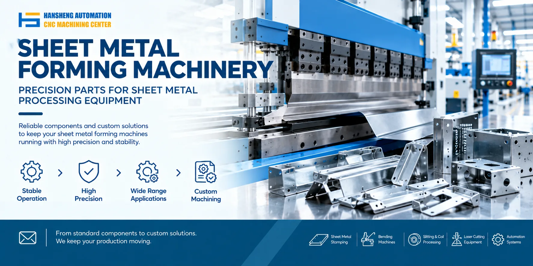
The ram of a CNC press brake must remain properly aligned with the worktable to maintain consistent bending accuracy. On many electro-hydraulic CNC press brakes, the Y1 and Y2 axes control the left and right sides of the ram. Linear scales measure their positions and send feedback to the CNC controller, which regulates the hydraulic cylinders to maintain synchronization. The exact adjustment method depends on the machine's control system and mechanical design. <Cite refs={["turn943318search32","turn943318search2"]}/>
How Ram Leveling Works on a CNC Press Brake
The leveling system typically consists of the ram, hydraulic cylinders, linear scales, and CNC controller.
The fixed scale of each linear measuring system is mounted to the machine frame, while the moving readhead or associated measuring component tracks the ram's position. The system measures the position of each side of the ram and sends the readings to the CNC controller.
When the controller detects a difference between the Y1 and Y2 positions, it compares the feedback with the programmed values. On machines equipped with independent hydraulic synchronization, the controller adjusts the corresponding hydraulic valves to correct the position difference.
This closed-loop control system helps keep the ram aligned with the worktable during movement. However, a leveling problem can also result from mechanical misalignment, guideway resistance, inaccurate reference settings, or faulty position feedback. Automatic correction cannot compensate for every mechanical fault.
Steps for Adjusting Ram Level
Start the control system
Switch on the machine and follow the manufacturer's startup procedure. Check the CNC controller for alarms and confirm that the hydraulic and position feedback systems are ready for operation.
Read the linear scale data
Check the displayed Y1 and Y2 position readings. Compare the values to determine whether the two sides of the ram are moving consistently.
If the readings fluctuate unexpectedly or do not correspond to the actual ram position, inspect the linear scales, mounting brackets, cables, and signal connections.
Check the position difference
The CNC controller compares the measured positions with the programmed reference values. If the difference exceeds the permitted range, the controller may generate a synchronization alarm or prevent further movement.
Confirm that the reference settings and feedback signals are correct before attempting mechanical or hydraulic adjustments.
Correct the hydraulic synchronization
On machines with independent hydraulic control of the two sides, the controller adjusts the corresponding valves to reduce the position difference between Y1 and Y2.
If automatic correction does not restore the required alignment, inspect the hydraulic circuit, valve response, cylinder condition, and mechanical guideways. Manual adjustment of synchronization parameters should follow the machine manufacturer's calibration procedure.
Verify the result
After adjustment, repeat the position check under the prescribed operating conditions. Confirm that the Y1 and Y2 readings are consistent and that the ram meets the manufacturer's alignment requirements.
Where necessary, use suitable measuring equipment to verify ram-to-worktable parallelism. Correct position readings alone do not establish that the tooling and worktable are mechanically aligned.
How to Troubleshoot a Tilted Ram
Check guideway lubrication and movement
Insufficient lubrication, contamination, or excessive friction in the guideways can prevent the ram from moving smoothly.
During initial installation and commissioning, inspect the guideways for contamination, dry surfaces, or signs of binding. Clean the relevant surfaces and apply the lubricant specified by the manufacturer.
Do not loosen the guideway fasteners without confirming the machine-specific adjustment procedure. Incorrectly tightening or loosening these fasteners can affect alignment and guide clearance.
Check the main motor and drive status
Start the hydraulic pump according to the machine's operating procedure and check the motor status, operating sounds, and displayed drive alarms.
If a fault appears when the machine is commanded to move, review the CNC controller and drive alarm records. An abnormal motor sound, a drive fault, or failure to establish hydraulic pressure requires further investigation.
Do not activate the foot switch while inspecting electrical equipment or reaching into the electrical cabinet. Any operational test must be performed with guards in place and according to the machine's safety procedures.
Check whether the valve block is energized
During an approved Y-axis homing or reference-return sequence, check the valve block indicators or diagnostic signals specified by the manufacturer.
If the expected indicator does not illuminate, inspect the control power supply, relevant wiring, fuses, and safety interlocks. The indicator behavior depends on the valve block design, so it should be interpreted using the correct electrical diagram.
Electrical inspection and repairs should be performed by qualified personnel.
Measure hydraulic pressure
If the ram remains tilted despite correct position feedback, check whether the hydraulic system is providing the required pressure to both sides.
A qualified technician can measure pressure at the designated test ports using suitable equipment and compare the readings with the machine manufacturer's specifications. If the pressure is outside the permitted range, investigate possible valve blockage, internal leakage, pressure instability, or other hydraulic faults.
Pressure gauges must be installed and removed according to the service procedure. Never loosen hydraulic fittings or connect unsuitable measuring equipment to a pressurized circuit.
Custom Precision Machining for Industrial Equipment
Hansheng Automation provides custom precision machining based on customer drawings for industrial applications. Our work includes components for yacht equipment and RC racing cars, as well as nonstandard parts for tobacco packaging and filling machinery. Each component is manufactured according to the supplied drawings and the specific requirements of the application.