Making a high-voltage cable joint requires careful preparation and precise installation of the insulation, stress-control, shielding, and protective layers. Each stage affects the electrical performance and reliability of the finished joint.
The following steps outline the process described in the source material. Exact preparation dimensions, component positions, and heating requirements must be checked against the specifications for the particular cable and joint kit. The approximately 30 mm dimension mentioned below should not be treated as a universal specification.
1. Prepare the cable ends
Prepare the high-voltage cable ends for joining. The source procedure mentions a preparation length of approximately 30 mm. Verify this dimension against the applicable cable and joint kit instructions before proceeding.
Carefully remove the outer black protective sheath while preserving the underlying protective layers. Avoid accidental cuts or damage to the insulation and other layers that must remain intact.
2. Position the heat-shrink components
Slide the large black insulating tubes supplied with the heat-shrink joint kit onto the cable ends in the required sequence. Position the tubes so they can be moved into place during the later stages of assembly.
Correct positioning before connecting the conductors helps prevent unnecessary handling of the prepared joint.
3. Apply stress-control components
Install the specially shaped, tapered stress-control sleeve, sometimes described as a pencil-shaped component. Its purpose is to help distribute electrical stress around the joint and reduce localized electric field concentrations.
Position the component according to the joint kit specifications to maintain the intended stress-control geometry.
4. Clean the conductor and semiconductive layers
Thoroughly clean the exposed conductor cores and semiconductive layers before applying the next materials. Remove surface contamination that could interfere with contact, insulation, or bonding.
Keep the prepared surfaces clean throughout the process to avoid introducing contaminants into the joint.
5. Apply stress-relief mastic and the stress-control tube
Wrap the specified stress-relief mastic or tape tightly around the cable end and the designated stress-control area. Then position the stress-control tube over the prepared section.
The mastic should cover the required areas evenly, following the arrangement specified for the joint kit.
6. Heat-shrink the stress-control tube
Apply heat evenly to the stress-control tube until it shrinks firmly into position. Avoid concentrating heat on one area for too long, and follow the heating method specified by the component manufacturer.
Check that the tube has recovered evenly and that the required areas are covered without obvious gaps.
7. Install the shielding and insulation layers
Fit the copper shielding mesh around the joint area. Then install the inner insulation, outer insulation, and semiconductive tubes in the sequence specified by the joint design.
Each layer has a distinct role in the joint structure. Correct positioning and overlap are necessary to maintain the intended insulation and shielding arrangement.
8. Connect and smooth the conductor joint
Connect the conductors using the specified compression connector and approved crimping equipment. After crimping, inspect the connection and remove sharp edges or protrusions where required.
A smooth connector profile helps reduce the risk of localized electrical stress. The finished connection must also meet the connector manufacturer's requirements.
9. Apply semiconductive tape and fill gaps
Wrap semiconductive tape around the designated area. Apply stress-relief mastic to fill the gaps around the tapered stress-control components where specified.
The materials should cover the required areas without leaving voids that could compromise the joint structure.
10. Heat-shrink the insulation layers in sequence
Heat-shrink the inner insulation, outer insulation, and outer semiconductive layer in the specified order.
Apply heat evenly to each component and check its position during installation. Follow the joint kit instructions for overlap, alignment, and heat application rather than assuming that every layer uses the same procedure.
11. Complete the shielding, grounding, and outer protection
Complete the copper shielding mesh connections and bond the grounding conductor according to the joint design. Position and shrink the remaining heat-shrink tubes to secure the assembly.
Apply heat to the outer protective layer until it fits properly around the joint. Once the protective layer has recovered, wrap the specified areas with black electrical tape as required by the procedure.
Before returning the cable to service, the completed joint must undergo the inspection and electrical tests required for the cable system. High-voltage jointing should be performed by qualified personnel using the applicable manufacturer instructions and safety procedures.
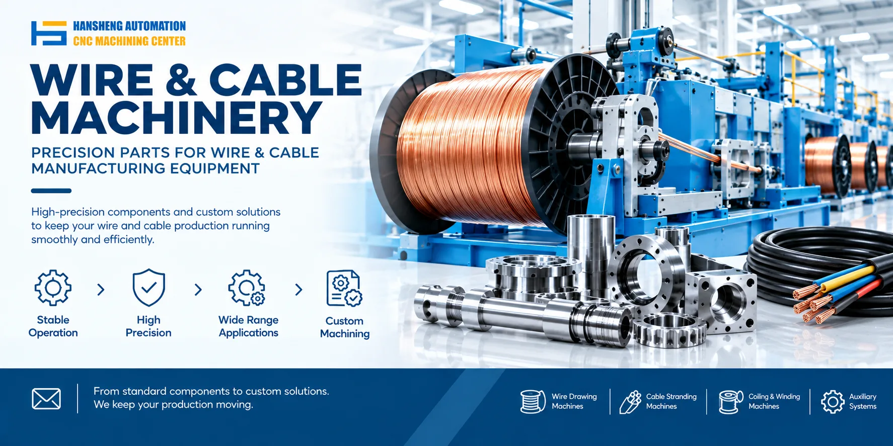
Custom precision machining for cable and industrial equipment
Cable production and installation equipment also relies on precision mechanical components, including mounting brackets, shafts, supports, and connecting parts. Hansheng Automation provides custom precision machining based on customer drawings, with manufacturing processes selected according to component geometry, material specifications, and dimensional tolerances.
Our drawing-based machining services also cover components for yacht equipment, RC racing cars, tobacco packaging machinery, and filling equipment. Customers can submit drawings and technical requirements for evaluation, whether they need individual prototypes or small batches of non-standard mechanical parts.