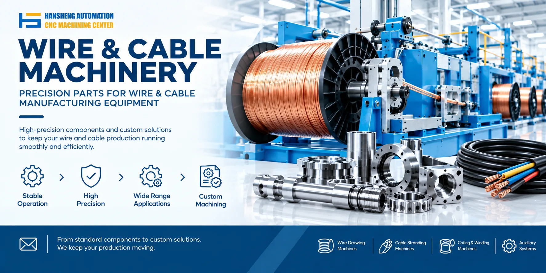
Rubber paper take-up setup on a wire drawing machine follows five steps: threading and positioning, tension matching, traverse centering, diameter matching, and fault checks. The goal is flat winding with no overlap and stable tension without slack. Disconnect the main power during the whole setup to prevent injury. Hansheng Automation can machine take-up shafts, guide rollers, tension wheels, and traverse devices from customer drawings, in single pieces or small batches.
1. Threading and positioning
Before threading, disconnect the main power of the take-up machine. Hang a warning sign that says "Machine under adjustment. Do not switch on." Only qualified maintenance personnel should do this work.
Core and guide roller positioning
Adjust the concentricity between the take-up core fixed shaft and the winding shaft to no more than 0.2 mm. Lock the shaft end lock nut to prevent winding movement.
Pass the rubber paper end through the take-up guide roller and tension sensor in order. Insert it into the core slot and fix it with the pre-tightening clamp to prevent slipping.
2. Tension matching
Tension parameter calibration
Set the threshold according to rubber paper thickness. For thin paper of 0.05 to 0.1 mm, set 1.5 to 2.5 N. For thick paper above 0.1 mm, set 2.5 to 4 N.
Run the take-up machine empty for 30 seconds. If tension fluctuation exceeds ±0.3 N, adjust the tension damping wheel gap slightly.
3. Traverse centering
Traverse position calibration
Adjust the traverse guide rod to the exact center of the core. Deviation should be no more than ±0.5 mm.
Run the take-up belt at low speed. If the rubber paper edge swings, adjust the traverse cam angle slightly to align with the core end face.
4. Diameter matching
Take-up speed matching
Set take-up speed to 0.8 to 1.0 times the wire drawing machine output speed. Output speed is usually 10 to 30 m/min. This avoids overlap caused by speed difference.
Measure winding thickness after each full turn. If error exceeds ±0.1 mm, adjust the traverse stroke.
5. Fault checks
Continuous winding check
After 10 continuous winding turns, check: if there are wrinkles, adjust tension. If there is overlap, adjust the traverse eccentricity slightly.
Stop the machine and check the core end face. There should be no bulge or dent. If there is, adjust the take-up shaft levelness.
Beyond wire drawing and take-up machines, our precision custom machining capability is not limited to one industry. Hansheng Automation can machine non-standard metal parts for medical devices, food filling equipment, tobacco packaging machinery, and printing equipment from customer drawings. We also machine yacht components and RC car components. We focus on build-to-print custom machining and produce single pieces or small batches according to customer drawings. We do not sell complete machines.