A cam-lifting roller conveyor is a non-standard automated system that combines a cam jacking mechanism with roller conveying. Its design uses the periodic motion of a cam to raise and lower materials vertically, while rollers and side guides handle horizontal transport and positioning.
I. Design Principles of the Cam Jacking Mechanism
Cam jacking is the core function for vertical lifting. It is based on the cam profile driving a follower-usually a lifting rod-in reciprocating linear motion, converting rotary motion into vertical displacement.
Cam profile design
The cam profile curve, such as constant velocity, constant acceleration/deceleration, cosine acceleration, or cycloidal motion, directly determines the motion of the lifting rod.
Constant velocity cam: the lifting rod rises or falls at uniform speed. It suits scenarios requiring uniform speed, but can produce rigid impact.
Cosine acceleration cam: smoother motion and lower impact, suitable for high-speed or heavy-load conditions.
The curve type should be selected according to material weight, lifting speed, and acceleration requirements. Mathematical modeling, such as cycloidal motion equations, can be used to optimize profile parameters.
Drive method and structure
The cam is usually driven by a motor. A reducer lowers speed and increases torque, and a coupling connects the reducer to the camshaft. A roller is installed at the contact end of the lifting rod to reduce friction. The rod body is guided by linear bearings or guide rails to ensure stable vertical movement.
Synchronization control
In multi-station conveying, multiple cam jacking mechanisms need to maintain phase consistency through timing belts or gear transmission. This ensures all lifting rods act synchronously and prevents material tilting or jamming.
II. Roller Conveying and Side Guide Applications
Roller conveying is responsible for horizontal material movement. Side guides limit material position and prevent deviation or falling. Together they achieve accurate positioning.
Roller conveying design
Roller arrangement: parallel arrangement is common. Roller spacing is designed according to material size, usually slightly smaller than the material length, to ensure stable support.
Drive method:
Drive rollers: powered by a motor through chains or belts, providing conveying power.
Idler rollers: rotated by friction between the material and the drive rollers, reducing energy consumption.
Surface treatment: rollers can be coated with rubber or polyurethane to increase friction and prevent material slipping.
Side guide structure design
Fixed side guides: installed on both sides of the rollers, fixed by bolts or welding. Suitable for fixed material sizes.
Adjustable side guides: guide spacing is adjusted through slide rails or threads to adapt to different material sizes, improving equipment versatility.
Guide materials: wear-resistant metal such as stainless steel or engineering plastics such as POM are commonly used to balance strength and cost.
Coordinated working logic
When the cam jacking mechanism lifts the material above the roller surface, the rollers stop rotating, and the material remains stationary under the limit of the side guides. After the jacking mechanism lowers, the material falls back onto the rollers and is driven by the drive rollers for continued horizontal conveying. Sensors such as photoelectric switches detect material position and feed back to the PLC control system for automated coordination.
III. Overall Design Points and Optimization Directions
Load capacity: select cam material, such as 45# steel with quenching and tempering, and roller diameter according to material weight to ensure structural strength.
Motion smoothness: optimize the cam profile curve, reduce sudden acceleration changes, and lower vibration and noise.
Maintenance convenience: design quick-release structures, such as retaining rings for roller fixation, for easy replacement of worn parts.
Energy-saving design: use variable frequency motors to drive rollers and adjust speed according to load, reducing energy consumption.
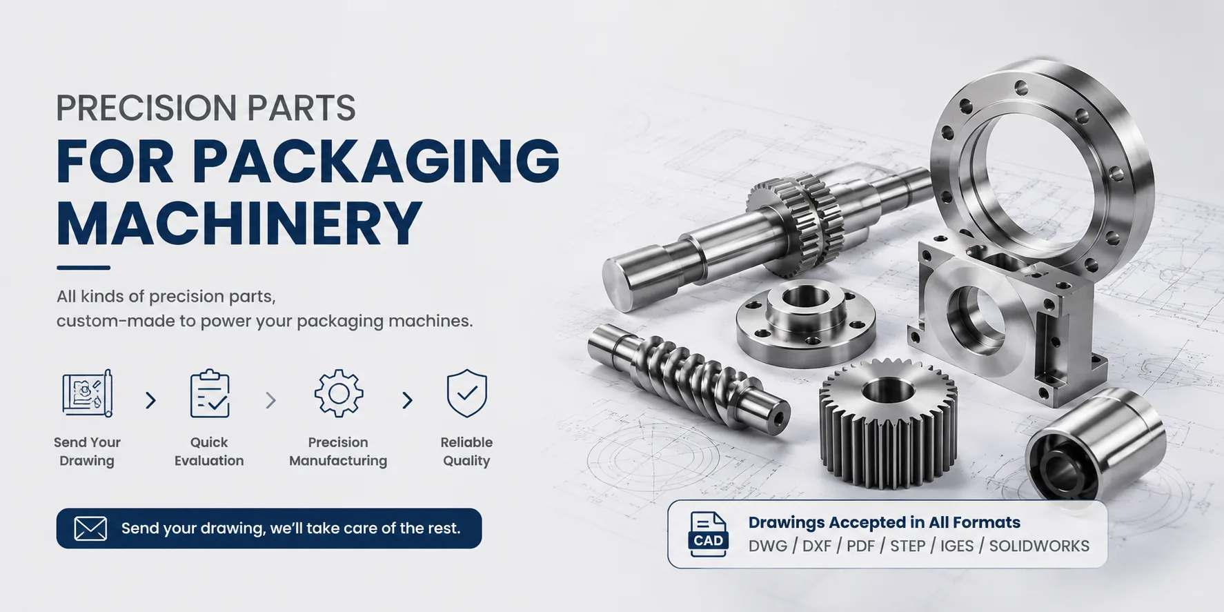
For cam plates, follower rollers, lifting rods, roller shafts, side guides, and adjustment brackets used in these conveyors, Hansheng Automation can machine non-standard parts from customer drawings in single pieces or small batches, with material, heat treatment, and surface finishing selected to match load and wear conditions.
IV. Application Examples
Packaging production lines: cam jacking lifts products, and roller conveying completes processes such as labeling and inkjet printing.
Assembly lines: side guides position materials for robotic arm picking or assembly.
Logistics sorting: combining lifting and conveying functions enables multi-directional material diversion.
Through the coordinated design of cam jacking and roller side guides, the equipment can efficiently complete combined vertical and horizontal material movement. It is suitable for non-standard automation scenarios requiring precise positioning and high-speed conveying.