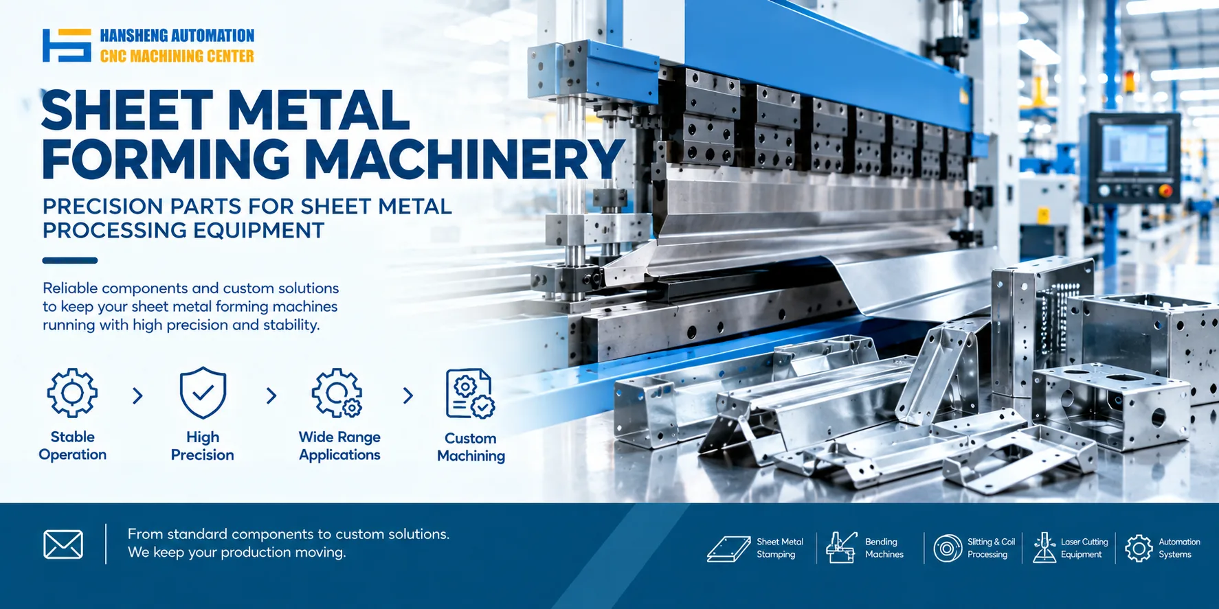
CNC press brake bending methods can be classified by tooling operation and workpiece shape. Air bending and bottoming differ in how the sheet metal contacts the dies, while L-bending, N-bending, Z-bending, hemming, and hardware insertion are selected according to the part geometry and forming requirements.
Air bending and bottoming
Air bending
In air bending, the upper die does not press the sheet metal fully against the bottom of the lower die's V-opening. The bend angle is controlled by adjusting how far the upper die enters the opening.
A deeper stroke produces a smaller bend angle, while a shallower stroke produces a larger angle. Because the material springs back after the load is released, the bending depth must account for springback to achieve the required final angle.
Air bending requires fewer dies to produce different bend angles and generally uses less bending force than bottoming.
The recommended relationship between material thickness and the lower die's V-opening width depends on the sheet thickness. For low-carbon steel with a strength of 43.4 kg/mm², the following ratios apply:
| Material thickness (B) | B ratio |
|---|---|
| Below 12.7 mm | 1:8 |
| 12.7 to 22.2 mm | 1:10 |
| Above 22.2 mm | 1:12 |
Here, B is the material thickness and V is the width of the lower die's V-opening.
Bottoming
In bottoming, the sheet metal is pressed firmly between the upper and lower dies to achieve the required bend angle and bend radius.
This method is suitable for batch and mass production of sheet metal parts less than 2 mm thick. It produces a small bend radius and high bending accuracy.
Bottoming requires substantially more force than air bending. The working pressure is generally more than three times that required for air bending. The die angle must match the required bend angle and the material being processed.
L-bending
L-bending produces an L-shaped profile. Based on the bend angle, it can be classified as 90° bending or non-90° bending. Based on the processing conditions, it is divided into general bending (L > V/2) and special bending (L ≤ V/2).
Die selection depends on the material, sheet thickness, and required bend angle.
The preferred positioning method uses two backgauges, with the workpiece positioned according to its external profile. Operators must account for possible misalignment, reverse-side positioning, and the selected positioning points.
The positioning method and backgauge movement must be checked for each setup to prevent the workpiece from shifting or deforming during bending.
When press brake equipment also requires nonstandard mechanical components, Hansheng Automation can machine precision parts to customer-supplied drawings.
N-bending
N-bending requires a forming method suited to the workpiece geometry. The internal dimension of the material must be greater than 4 mm. Smaller dimensions require a special processing method.
Select the dies according to the material thickness, dimensions, material type, and bend angle.
The workpiece must clear the tooling throughout the bending operation. The positioning angle should be slightly less than 90°, and using two backgauges is preferred when the part geometry permits.
After the first L-bend, the angle should be 90° or slightly less. For the second bend, position the workpiece with reference to the center of the previously machined surface.
Z-bending
Z-bending, also called offset bending, creates two bends in opposite directions.
The minimum workable dimension is limited by the tooling, while the maximum dimension depends on the external dimensions of the machine.
The positioning method should provide convenient access and stable support. The initial positioning method is generally the same as that used for L-bending. For the second positioning operation, the workpiece must sit flat against the lower die.
The first L-bend must reach the required angle before the second bend begins. If the backgauge must retract, check whether this movement could deform the workpiece. The bending sequence must also be appropriate for the part geometry.
Reverse bending and flattening
This process is also known as hemming. The sheet metal is first bent to approximately 35° using an insertion die. A flattening die is then used to close the bend until the edges lie flat and tight against each other.
For the initial bend, select a 30° lower die with a V-opening width of 5 to 6 times the material thickness. Choose the upper die according to the specific hem dimensions and forming conditions.
The two sides of the hem must remain parallel. For a long hem, bend a small raised angle before flattening the edge. For a short hem, a shim can be used during processing.
Pressing hardware into sheet metal
Hardware installation uses a press brake to press or rivet hardware into a workpiece. The operation generally requires auxiliary tooling such as dies and jigs.
Typical applications include pressing in nuts, studs, screws, and other metal hardware.
If the workpiece profile requires clearance around the hardware, provide the necessary relief before processing. After installation, check whether the torque and push-out force meet the applicable requirements. The hardware must also sit flat and tight against the workpiece.
When hardware is installed after bending, check the available clearance and die parallelism. During expansion riveting, inspect the expanded edge for cracks and make sure it does not protrude above the workpiece surface.
Custom precision machining for industrial equipment
In addition to supporting sheet metal equipment with custom machined mechanical components, Hansheng Automation provides precision machining based on customer drawings for a range of industries. These components include parts for yacht equipment and RC racing cars, along with nonstandard components for tobacco packaging, filling, and printing machinery. Manufacturing requirements are assessed according to the supplied drawings and the specifications of each part.