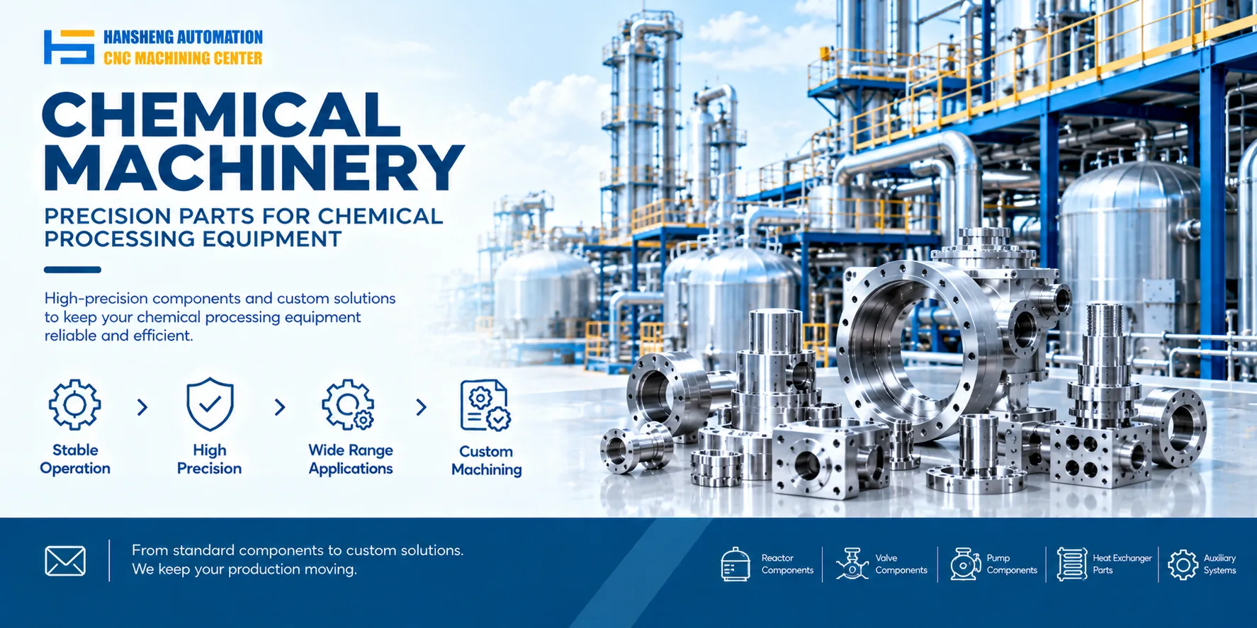
Industrial reactors are commonly equipped with agitation drive systems, material handling equipment, temperature control systems, safety protection devices, and process monitoring and control systems. These systems support feeding, mixing, heating, cooling, reaction, and discharge operations.
The required equipment depends on the reactor volume, operating pressure, temperature range, process medium, and level of automation. Not every reactor requires the same configuration.
Drive and sealing equipment
Agitation drive system
The agitation drive system transfers power from the motor to the agitator shaft, allowing the agitator to operate according to process requirements. A typical configuration includes a drive motor, gearbox, coupling, and associated support components.
A variable frequency drive can be used when the agitation speed needs to be adjusted. For reactors installed in hazardous areas where explosive gas atmospheres may be present, electrical equipment must be selected according to the hazardous area classification and applicable requirements. An explosion proof motor is not a standard requirement for every reactor.
For high viscosity materials or applications with substantial starting loads, check the motor power, gear ratio, output torque, and shaft loading to ensure that the drive system meets the actual mixing requirements.
Shaft seals and support components
The point where the agitator shaft passes through the vessel wall typically requires a sealing arrangement to control process medium leakage. Common options include packing seals, single mechanical seals, and double mechanical seals. Some reactors use magnetic coupling drives.
Packing seals have a relatively simple structure, but their suitability depends on operating pressure, temperature, medium properties, and leakage control requirements. Mechanical seals are available in different configurations. Double mechanical seals can also be equipped with a suitable barrier or buffer system.
Magnetic coupling drives can be considered for applications where reducing leakage risks associated with a rotating shaft penetration is a priority.
Seal selection should not be based solely on whether the reactor operates at atmospheric or elevated pressure, or whether the process medium is toxic. Corrosivity, operating temperature, pressure, agitation speed, and the allowable leakage level must also be considered.
Frames, bearing housings, and related support components maintain the position and stability of the agitator shaft. Their design must match the shaft, drive arrangement, and actual operating loads.
Material handling equipment
Material handling systems cover feeding, metering, pretreatment, and discharge. The required equipment depends on the physical form of the raw materials, their flow characteristics, the required feeding accuracy, and the production cycle.
Solid feeding systems
Small reactors may use manual charging ports with suitable dust covers and local extraction provisions. Medium and large reactors, or those used in highly automated production lines, may use vacuum conveying systems, screw conveyors, weigh hoppers, or automatic feeding stations.
For powders that generate dust, absorb moisture, or tend to form lumps, consider enclosed conveying, sealed feeding connections, and suitable dust collection measures. When accurate dosing is required, select an appropriate weighing or metering system. Material level detection alone does not directly measure the actual feed quantity.
Liquid feeding systems
Liquid raw materials can be fed into a reactor using metering pumps, transfer pumps, or elevated feed tanks. Where the process requires the removal of particulate contaminants, a suitable filter can be installed in the pipeline.
Metering pumps are used when the feed rate needs to be controlled. The pump must be selected according to liquid viscosity, corrosivity, required flow rate, and operating pressure. Elevated feed tanks can provide buffering or supply liquid through gravity, depending on the system design.
For processes that require accurate formulation ratios, weighing systems, flow meters, or other suitable metering methods can also be used.
Gas feeding systems
When a process requires nitrogen or another inert gas, or a gas that participates in the reaction, the feeding system may include pressure reducing valves, flow meters, buffer tanks, and associated pipeline valves.
For accurate gas flow control, select a suitable flow meter or mass flow controller according to the gas properties, flow range, and operating pressure. When handling flammable or toxic gases, also consider check valves, backflow prevention, leak detection, and the necessary safety interlocks.
Discharge systems
For materials processed under atmospheric pressure or materials with low viscosity, a bottom discharge valve or another suitable discharge device can be used, depending on the reactor design. The valve type must match the material properties, pressure conditions, and sealing requirements.
For high viscosity materials, a screw pump, diaphragm pump, or another suitable transfer pump can be selected according to the material's flow characteristics and required discharge pressure. For heat sensitive materials, the choice should also account for the allowable temperature, discharge time, and shear effects during transfer. The pump type alone does not determine whether material degradation can be prevented.
Some processes use vacuum assisted discharge. Before adopting this arrangement, verify that the reactor and associated pipelines are designed to withstand the required internal pressure or external pressure conditions. Material volatility and system sealing must also be considered.
Material pretreatment equipment
For processes that require premixing, dispersion, or emulsification before materials enter the reactor, a static mixer, emulsifier, or other suitable pretreatment equipment can be installed.
A static mixer uses fixed internal mixing elements to promote mixing as fluid passes through it. An emulsifier is used when the process requires further dispersion of droplets or treatment of a particular multiphase system. The need for pretreatment depends on raw material compatibility, mixing requirements, and subsequent reaction conditions.
Temperature control and solvent recovery equipment
A reactor temperature control system generally includes heating or cooling media, circulation equipment, temperature sensors, and a control unit. Its configuration depends on the reaction temperature, required heating and cooling rates, heat generation, and process stability requirements.
Heating systems
Depending on the reactor design, heating can be provided by electric heaters, steam, circulating thermal oil, or another suitable heat transfer method.
Small units may use electric heating elements. Industrial reactors commonly transfer heat through a jacket or internal coil. For steam heating, the supply conditions, heat transfer area, and process requirements must be considered. For thermal oil heating, a dedicated temperature control unit or circulating heating system can regulate the heat transfer fluid temperature.
For higher temperature processes, a specialized high temperature heat transfer system may be required. Molten salt and other high temperature media are suitable only for systems designed to meet the corresponding material, sealing, circulation, and safety requirements. A single maximum temperature should not be applied to all reactor designs.
Cooling and temperature control systems
When a reaction requires cooling or the removal of reaction heat, a jacket, internal coil, or external circulation heat exchanger can be used. Common cooling media include cooling water, chilled water, water based antifreeze solutions for low temperature applications, and other suitable heat transfer fluids.
For processes that require heating and cooling across a wide temperature range, a circulating temperature control unit can regulate the heat transfer fluid temperature and flow rate according to the setpoint.
The achievable temperature range depends on the heat transfer medium, temperature control equipment, heat exchange structure, and overall system design. Selection should take into account the minimum and maximum operating temperatures, circulation pressure, heat transfer capacity, and compatibility between the fluid and piping materials. A fixed temperature range should not be assumed suitable for every reactor.
Condensation and solvent recovery systems
For processes that generate condensable vapors, a condenser, reflux receiver, and associated piping can be installed where required.
The condenser converts suitable vapors into liquid. Depending on the process, the condensate can be returned to the reactor or collected for subsequent recovery or treatment. The configuration depends on solvent properties, vapor flow rate, cooling conditions, and material recovery requirements.
For flammable or toxic media, the design should also address vapor containment, exhaust treatment, and other safety measures identified by the risk assessment. A condenser alone does not provide complete emission control.
Safety protection equipment
Safety provisions must be determined according to the reactor design pressure, operating temperature range, hazardous properties of the process medium, and potential process upset conditions. Different protective devices serve different functions and must be selected as part of the overall system design.
Pressure monitoring and overpressure protection
Pressure gauges and pressure transmitters monitor vessel pressure and can send readings to the control system. Where overpressure is a credible hazard, safety valves, rupture discs, or engineered combinations of these devices may be required under applicable pressure vessel requirements and process risk assessments.
A safety valve releases pressure when its set conditions are reached. A rupture disc provides pressure relief by opening at a predetermined burst pressure. Device selection, required relief capacity, and the discharge destination must be determined according to the potential overpressure scenarios, medium properties, and equipment design conditions.
Processes that may experience runaway heat generation, rapid gas production, or the release of toxic media require particular attention to relief system design. A relief device alone cannot guarantee that an accident will be prevented. Proper capacity calculations, installation, maintenance, and safe discharge arrangements are also necessary.
Temperature monitoring and overtemperature protection
Thermocouples or resistance temperature detectors can measure reactor temperature. A temperature controller or automated control system can then regulate heating and cooling.
For processes with an overtemperature risk, an independent high temperature alarm or interlock can be installed. When the specified limit is reached, the system can stop heating or initiate a predefined safety action.
Whether the cooling system should also start automatically depends on the reaction characteristics and risk analysis. For some exothermic reactions, switching on cooling alone may not control a runaway reaction. The protection logic must therefore be designed for the specific process.
Gas detection and emergency shutoff devices
For processes involving flammable gases, toxic gases, or hazardous vapors, combustible gas detectors or toxic gas detectors can be installed at suitable locations according to the medium properties and site risk assessment.
In an abnormal situation, an emergency shutoff valve can close the relevant feed line according to the configured control logic, reducing the amount of additional material entering the system. The actuation conditions, fail safe position, and control power requirements must be established as part of the process safety design.
Flame arresters limit flame propagation in systems for which they are designed. They should not be treated as universal explosion protection devices for reactors. Rupture discs provide pressure relief and should not be confused with dedicated explosion venting systems.
Emergency shutdown and response facilities
Depending on the process, a reactor may be equipped with an emergency stop button, audible and visual alarms, and associated safety interlocks. Processes that present a risk of runaway reactions or hazardous material release may also require specially designed emergency quench systems, backup cooling, or containment facilities.
An emergency discharge tank is not a standard requirement for every reactor. Whether one is needed, and how material should be transferred in an emergency, must be determined through engineering assessment of the material hazards, reaction state, relief conditions, and emergency response plan. An inadequately designed emergency discharge arrangement can introduce additional risks.
Instrumentation and automatic control systems
Instrumentation and control systems monitor critical process variables and adjust equipment operation according to process requirements. Individual instruments should be selected according to the parameters that need to be measured or controlled.
Process parameter monitoring
Common measurements include temperature, pressure, liquid level, and flow rate. Processes that require control of acidity or solution composition may also use pH meters, conductivity meters, and other suitable analytical instruments.
For materials whose viscosity changes significantly during processing, a suitable viscometer may be installed. Changes in agitator torque or motor load can also provide supplementary process information. However, torque changes alone cannot confirm that a reaction is complete, because the load may also be affected by liquid level, agitation speed, and material condition.
Instrument location, measurement range, corrosion resistance, and measurement method must be compatible with the process medium and operating conditions.
PLC control systems
A programmable logic controller (PLC) can be used for a single reactor or a small group of reactors, depending on the automation requirements. It can coordinate feeding sequences, agitator operation, temperature control, valve actuation, discharge, and fault alarms.
Control programs should define operating sequences, parameter limits, and the necessary interlocks according to the process. For higher risk reactions, the risk assessment should determine whether an independent safety instrumented system is required. A standard process control program should not automatically be assumed to provide all required safety functions.
DCS and human machine interfaces
For multiple reactors or more complex continuous and batch production processes, a distributed control system (DCS) can monitor operating parameters, process status, and alarms across multiple units.
An industrial touchscreen or another human machine interface allows operators to set parameters, view operating status, acknowledge alarms, and investigate faults. Depending on production requirements, the system may also need data logging, access control, and communication interfaces.
How to determine the required reactor equipment
Reactor equipment should be selected according to the actual process rather than by installing every available option. Before making a selection, define the physical and chemical properties of the materials, reaction temperature and pressure, agitation load, heating and cooling requirements, feeding accuracy, and discharge method.
For processes involving flammable, toxic, or highly corrosive media, or those that may undergo vigorous exothermic reactions, carry out the appropriate risk assessment to determine the sealing, pressure relief, monitoring, interlocking, and emergency response requirements. The drive system, temperature control system, and safety devices must also be assessed as an integrated system to ensure that they operate together under the specified conditions.
In addition to precision components for reactor equipment, we provide custom machining services for a range of industries. Based on customer supplied drawings, we manufacture parts for tobacco packaging machinery and filling equipment, as well as precision components for yachts and radio controlled racing cars. The machining scope depends on the component design, dimensional requirements, and technical specifications provided in the drawings.