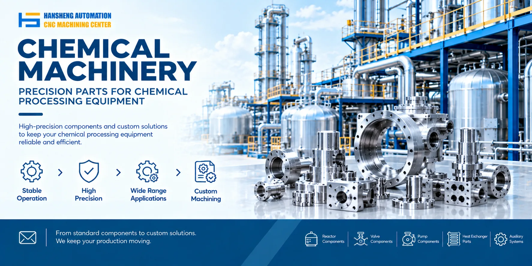
Level 2 maintenance of a reactor vessel generally covers the drive system, vessel body and supports, sealing system, electrical and instrumentation systems, process piping, safety accessories, and post-maintenance testing. The specific tasks should be determined according to the equipment design, operating history, process media, and manufacturer's maintenance instructions. Repairs or modifications to the pressure boundary, as well as statutory inspections, must comply with the applicable regulations and technical specifications for special equipment. These activities should not be treated as routine mechanical maintenance.
Preparation Before Maintenance
Before maintenance begins, develop a work plan based on the reactor vessel's media, temperature, pressure, and structural design. Define the maintenance scope, personnel responsibilities, isolation measures, and acceptance criteria.
Stop the equipment and ensure that the internal pressure and temperature have reached safe levels for the planned work. Drain the remaining process material, then clean, purge, and ventilate the vessel according to the properties of the media. Disconnect the power supply to the agitator motor and associated auxiliary equipment. Apply lockout/tagout (LOTO) procedures to prevent accidental startup. Connected hazardous-media lines must also be reliably isolated according to the risks involved.
If personnel need to enter the vessel, follow the applicable confined-space entry requirements. These may include atmospheric testing, ventilation, an assigned attendant, and emergency preparations. For enterprises subject to GB 30871-2022, Safety Specifications of Special Work in Hazardous Chemicals Enterprises, closing valves alone may not satisfy the required pipeline isolation measures.
Mechanical Structure Maintenance
Drive System Inspection
Inspect the motor, gearbox, coupling, drive belts, bearings, and agitator shaft. Check the gearbox lubricant level, condition, and signs of leakage. If the oil is emulsified, contaminated, or deteriorated, replace it with the grade specified by the manufacturer.
Inspect gears, bearings, couplings, and drive connections for abnormal wear, looseness, excessive clearance, or damage. Measure the agitator shaft's radial runout and axial movement, then compare the results with the equipment drawings, technical documentation, or specified maintenance limits. A single runout value should not be used to assess all reactor shafts.
Check the agitator blades, mounting bolts, and connecting structures. Cracked or visibly deformed blades, excessive corrosion or material loss, and loose fasteners require assessment and appropriate repair or replacement. Before carrying out on-site welding repairs to load-bearing components, evaluate the defect and establish an approved repair procedure.
Vessel Body, Jacket, and Supports
Remove accumulated material from the inner and outer surfaces of the vessel. Inspect the shell, heads, welds, connections, and supports for corrosion, cracks, deformation, and other defects. Where localized corrosion is found, measure the remaining wall thickness as needed and compare the results with the design requirements and minimum allowable wall thickness. The vessel's safety should not be determined solely by whether the measured corrosion loss has reached a fixed percentage of the original wall thickness.
For glass-lined or plastic-lined reactor vessels, inspect the lining for cracks, blistering, peeling, pinholes, and other damage. Treat any defects using a repair procedure suitable for the lining material and approved by the equipment manufacturer. Improper grinding, welding, or tool impact can cause further damage.
Check the supports, anchor bolts, foundation, and connecting welds. Tighten loose bolts according to the specified requirements. If foundation settlement, cracked welds, or support deformation is found, identify the cause before developing a repair plan. Defects involving pressure-retaining parts or important load-bearing structures should be assessed and handled by a qualified organization with the necessary technical capabilities.
For jacketed reactor vessels, inspect the jacket piping, inlet and outlet connections, drain valves, and circulation passages for blockage or leakage. If a pressure test or other pressure-related test is required, determine the test medium, pressure, and holding requirements from the equipment design documents, applicable codes, and approved test procedure. A single test pressure expressed as a fixed multiple of the design pressure should not be applied to every vessel.
Sealing System Maintenance
Mechanical Seal Inspection
When dismantling a mechanical seal, inspect the rotating and stationary seal faces, springs, secondary sealing elements, and other components for wear, cracks, corrosion, deformation, or loss of elasticity. Check the shaft sleeve for surface wear, corrosion, and scoring.
Whether a component can be reused should be determined from the manufacturer's dimensional limits, fit requirements, and the condition of the sealing assembly. A single wear limit for the seal faces or a fixed scoring depth for the shaft sleeve is not suitable for all reactor vessels.
Before reassembly, clean the seal chamber and related components. Check the shaft and sealing assembly for proper fit, then follow the specified assembly sequence, dimensions, and installation requirements. If a lubricant or seal support fluid is required, confirm its compatibility with the sealing materials and process media.
After maintenance, verify sealing performance under the specified test conditions. The acceptable leakage rate depends on the seal design, media properties, operating pressure and temperature, and manufacturer's requirements. A fixed number of liquid drops or gas bubbles per minute should not be treated as a universal acceptance criterion for all liquid and gas services.
Packing Seal Inspection
For reactor vessels using packing seals, inspect the packing gland, stuffing box, and the mating surface of the agitator shaft. Before installing new packing, remove the old material and residue, then check the shaft for wear and corrosion.
Select packing according to the process media, operating temperature and pressure, shaft speed, and material compatibility. Install the new packing and tighten the gland evenly according to the specified procedure. Excessive compression can increase friction and shaft wear, while insufficient compression can impair sealing. After maintenance, check for leakage and confirm that the seal operates properly. Adjust the packing as needed based on actual operating conditions.
Electrical and Instrumentation Maintenance
Before electrical work, verify that the equipment has been reliably de-energized and that lockout/tagout and absence-of-voltage verification procedures have been completed. Variable-frequency drives, sensors, and other electronic components must also be isolated and protected as required by their equipment instructions.
Inspect motor terminals, junction boxes, cables, and grounding connections for looseness, oxidation, corrosion, or insulation damage. Check the cooling fans, ventilation passages, and filters of the variable-frequency drive. Remove accumulated dust and review alarm records and operating status.
Motor insulation testing should use an appropriate instrument and test method. Evaluate the results against the motor's rated parameters, manufacturer's requirements, environmental conditions, and applicable electrical testing standards. A fixed insulation resistance threshold measured at a single megohmmeter voltage should not automatically be applied to every motor. Before testing, isolate the motor from electronic equipment that could be affected by the test voltage. Restore the connections as required after testing.
Inspect the wiring, indication, and alarm functions of temperature, pressure, level, and other process instruments. Calibrate instruments according to their measurement ranges, accuracy requirements, operating environments, and calibration schedules.
For electrical equipment installed in hazardous areas, inspect the explosion-protected enclosure, flameproof joint surfaces where applicable, fasteners, cable entries, and grounding connections. These items must meet the requirements for the equipment's explosion-protection design. Repairs to explosion-protected components must not be carried out as though they were ordinary electrical repairs.
Inspect the grounding system for connection integrity and corrosion. The acceptable grounding resistance must be determined from the electrical system design, applicable standards, and requirements for the hazardous area. One resistance value should not be applied universally.
Process Piping and Safety Accessories
Process Piping Inspection
Inspect the feed, discharge, vent, return, and jacket circulation lines. Check welds, flanged connections, valves, gaskets, and pipe supports for leakage, corrosion, blockage, and abnormal deformation.
When dismantling flange connections, clean the sealing surfaces and inspect the gaskets for aging, damage, or incompatibility with the process media. Replace defective gaskets and tighten the flange bolts according to the applicable connection requirements and tightening procedure. Uneven bolt loading can cause leakage.
For corroded piping, measure the wall thickness where necessary and assess whether replacement is required based on the design requirements and minimum allowable wall thickness. A fixed percentage of wall thickness loss alone is not sufficient to determine whether a pipe section must be replaced or can remain in service.
Safety Accessory Inspection
Inspect safety valves, rupture disks, pressure gauges, thermometers, emergency shutoff valves, vent valves, and drain valves.
The set pressure of a safety valve must be determined from the protected equipment's design conditions and applicable safety technical specifications. Calibration or testing must be carried out by an organization or personnel meeting the relevant requirements. A fixed multiple of the design pressure should not be applied universally, nor should a single reseating-pressure ratio be used as the acceptance criterion for every safety valve.
For rupture disks, check the model, specification, installation direction, compatibility with the process media, and service condition. Inspection or replacement should follow the product requirements and equipment maintenance plan. Safety valves and rupture disks are different types of pressure-relief devices and should not be assessed using the same testing or acceptance procedure.
For pressure gauges and thermometers, inspect their condition, readings, ranges, connections, and calibration or verification status. Accuracy classes and calibration intervals must meet process requirements and applicable metrology regulations. A single accuracy class or a universal six-month interval should not be applied to all instruments.
After maintenance, confirm that the valves operate correctly and that their connections show no abnormal leakage. Verify that instrument indications and alarm functions meet the specified requirements. Retain the relevant records and certificates for any safety accessories that have been dismantled, calibrated, tested, or replaced.
Post-Maintenance Testing and Acceptance
After completing the work, restore all removed components according to the maintenance checklist. Confirm that tools, temporary supports, and debris have been removed and that guards and other safety devices have been correctly reinstalled. Replenish lubricants and seal support fluids as specified in the equipment manual. Check valve positions, piping connections, and electrical wiring.
If the maintenance involves the pressure boundary, jacket, or process piping, determine whether a pressure test, leak test, or other inspection is required based on the repair scope, design documents, and applicable regulations. The test pressure, medium, holding time, and acceptance criteria must be supported by a defined procedure. In particular, a pneumatic test must not be based solely on a standard pressure multiplier without an appropriately assessed test plan.
Conduct the test run according to the manufacturer's instructions. Where the equipment design and operating conditions permit, first check the drive and agitation systems, then proceed to verification under load or process conditions. Focus on the following points:
Check the agitator shaft, gearbox, and bearings for abnormal noise, vibration, or temperature rise.
Inspect the mechanical seal, packing seal, flanges, and piping connections for abnormal leakage.
Confirm that process parameters such as temperature, pressure, and agitator speed remain stable, and verify that instrument readings and interlock functions operate correctly.
Check the motor, variable-frequency drive, and associated control equipment for alarms or abnormal operating conditions.
Bearing temperature, test-run duration, vibration limits, and leakage acceptance criteria must be taken from the manufacturer's documentation, approved maintenance procedure, and applicable standards. A fixed operating time or temperature limit should not be treated as a universal requirement for all reactor vessels. If an abnormal condition occurs, stop the test run and identify the cause rather than extending the operating time as a substitute for troubleshooting.
Maintenance Records and Future Planning
After maintenance, compile the records. At a minimum, document the equipment identification, maintenance date, personnel involved, inspection items, measurement results, defects and corrective actions, replacement parts, test or calibration results, and acceptance decision.
For recurring faults, record the conditions under which they occurred and the actions taken. These records can help identify underlying causes such as corrosion, wear, inadequate lubrication, installation misalignment, or process fluctuations.
Schedule the next Level 2 maintenance based on the equipment manual, the company's maintenance system, operating load, and fault history. The interval should not automatically be set at three to six months for every reactor vessel.
Level 2 maintenance is not limited to replacing worn parts. It must also confirm that the vessel structure, seals, electrical systems, piping, and safety accessories remain suitable for the intended operating conditions. Maintenance tasks and acceptance limits should be supported by equipment documentation, measurement results, or applicable regulations. The repair method and pressure-test parameters for pressure-retaining components must not be set arbitrarily.
Regulatory Reference Note
The applicable regulatory requirements should be checked before this article is used as a formal maintenance procedure. In particular, verify the current version of TSG 21-2016, including its amendments, and the requirements that apply to the specific vessel and maintenance work.