When a vacuum packaging machine fails to reach or hold the required vacuum level, the cause is rarely a single defective part. More often, it involves a combination of factors across the pneumatic circuit, electrical controls, mechanical seals, and sensing systems. The following seven areas cover the most common failure points, with practical diagnostic methods for each.
1. Vacuum pump system
The pump is the primary source of negative pressure. Its operating condition determines both the ultimate vacuum level and the pumping rate.
- Oil level and quality: Check the sight glass. The oil should be between the MIN and MAX marks. If it is below MIN, top up with the manufacturer‑specified vacuum pump oil – do not mix different viscosities. Milky or dark oil indicates moisture or contamination; drain and flush the system before refilling.
- Operating temperature: Under continuous running, the pump housing surface temperature should not exceed 80 °C. Overheating may result from poor cooling, a clogged exhaust valve, or prolonged heavy load.
- Unusual noise: Normal operation produces a steady low hum. A sharp metallic screech suggests bearing wear or rotor rubbing; a periodic clattering noise may point to a broken vane.
2. Sealing bar assembly
The sealing bar not only performs heat sealing but also helps maintain chamber integrity during the vacuum cycle.
- Visual inspection and thickness: Food‑grade silicone sealing bars can deform or crack over time. If the working surface has worn down by more than 1 mm, the resilience is significantly reduced and replacement is needed. When the original cross‑section is no longer available, you can order custom‑made bars with the proper hardness (Shore A 60±5) and profile to fit your groove dimensions.
- Elasticity test: Press the bar with your finger; it should spring back within 3 seconds. A slower return indicates silicone ageing.
- Groove cleanliness: Remove the bar and check for trapped debris (e.g., rice grains, bone fragments, paper dust) that can cause localised gaps.
3. Vacuum chamber lid and locking mechanism
The lid must close tightly to preserve chamber vacuum.
- Gap measurement: With the lid closed, use a feeler gauge to check the clearance between the lid and the lower chamber. A gap exceeding 0.5 mm at any point points to wear or deformation in the latch or hinge.
- Simple air‑tightness test: Place a sheet of A4 paper across the sealing area, close the lid, and start the vacuum cycle. If you can pull the paper out easily, the chamber is leaking – inspect the lid flatness or replace the gasket.
- Lid flatness: Glass or polycarbonate lids may warp under heat and pressure. Measure diagonally with a straightedge; if the flatness deviation exceeds 2 mm, the lid should be straightened or replaced.
4. Solenoid valve group
Solenoid valves sequence the evacuation, venting, and sealing actions. A stuck valve or burned coil will prevent vacuum build‑up.
- Coil resistance: Measure the DC resistance with a multimeter. Typical values are around 27±5 Ω (refer to your model's specification). An open circuit indicates a broken coil; a significantly lower reading suggests a shorted turn.
- Valve body cleaning: Remove the valve and inspect the diaphragm or spool for oil sludge or gum deposits. Soak in anhydrous ethanol, then blow dry with compressed air – take care not to damage the sealing faces.
- Audible click: When energised, the valve should produce a crisp "click". If silent or muffled, check the drive voltage and mechanical freedom of the spool.
5. Vacuum sensor
The sensor converts chamber pressure into an electrical signal. Drift in its calibration can mislead the controller.
- Output voltage check: At atmospheric pressure (no vacuum), the output should be 4.8–5.2 V (corresponding to 0 kPa). At full vacuum it should approach 0 V. Large deviations require recalibration or replacement.
- Tubing connection: The sensor is usually connected to the chamber by a 4‑mm‑ID silicone hose. Ensure the hose is not loose, kinked, or blocked.
- Response time test: From start‑up to reaching –90 kPa, the system should take no more than 8 seconds. If longer, check not only the sensor but also pump efficiency and system leaks.
6. Piping and fittings
Small air leaks in the vacuum lines – at quick‑connect joints, corrugated tubes, or elbows – can ruin the vacuum.
- Quick‑connect fittings: Inspect each O‑ring for missing, aged, or distorted conditions. Fluororubber or silicone rubber O‑rings are preferred for better oil and temperature resistance.
- Corrugated tube condition: Flexible sections that bend frequently may develop hairline cracks after more than 2,000 cycles. A pressure‑hold test can reveal such leaks: evacuate the system to the set point, stop the pump, and monitor the pressure for 5 minutes – a drop of more than 5 kPa indicates leakage.
- Whole‑line leak detection: For hidden sections, use an ultrasonic leak detector or apply soapy water (with proper electrical protection) to find the leak.
7. Control board and relays
The main board issues the commands to run the pump, and the relay contacts switch the pump power. Faults here can prevent the pump from starting or cause it to stop prematurely.
- Relay contacts: Power off the machine and remove the relay. Inspect the contacts – if the burned area exceeds 30 % of the total contact surface, the contact resistance will be too high; replace the relay with an identical type.
- Pump terminal voltage: During the evacuation cycle, measure the voltage at the pump power terminals. It should be within 220 V ± 10 % of the rated value. Low voltage reduces pump speed and suction capacity.
- Error code interpretation: Most controllers display fault codes. For example, "E1" often means vacuum timeout – the set vacuum level was not reached within the allowed time. This calls for a comprehensive check across all the areas listed above.
Preventive maintenance and custom parts support
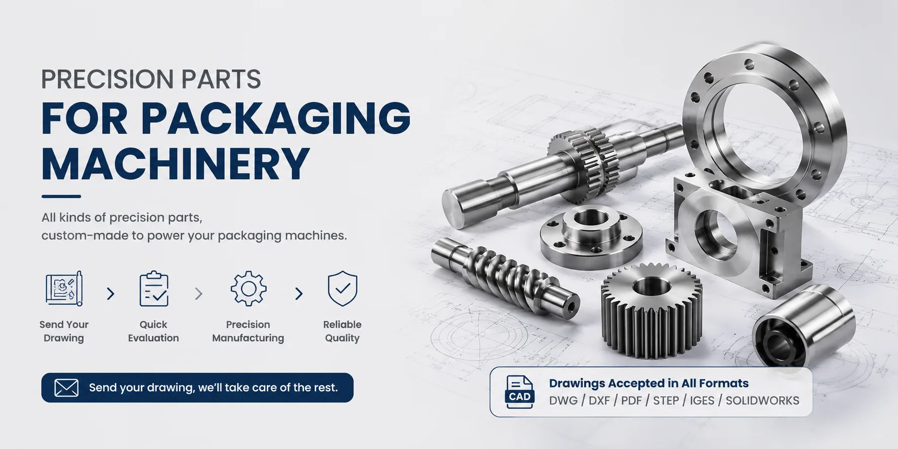
Regular inspections according to the above steps greatly reduce unexpected failures. In practice, however, you may find that sealing bars, sensor adaptors, valve spools, or other parts no longer match the original specifications – or you may need upgraded materials for harsh conditions (high temperature, high humidity, corrosive gases). In such cases, we can manufacture single pieces or small batches of custom components to your drawings – for example, pump couplings, seal retainers, sensor fittings, or flange adaptors. Materials available include aluminium alloy, stainless steel 304/316L, and engineering plastics, with surface treatments such as anodising, nickel plating, or PTFE coating to suit different hygiene and corrosion resistance requirements. This approach restores – and even improves – machine performance without the expense of a full replacement.
Safety notes
Always drain the pump oil and allow the pump to cool before disassembly. Disconnect the main power before any electrical work. When replacing seals, use food‑grade materials that comply with FDA or GB 4806 standards – never use ordinary industrial rubber. For precision‑fit parts, keep the original drawings or have the dimensions professionally measured before ordering custom‑machined components to ensure accurate mounting and tolerances.