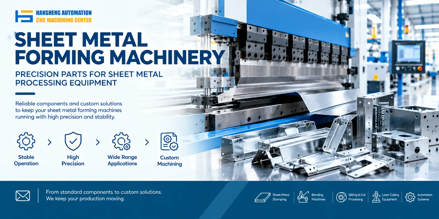
A CNC shearing machine consists of several mechanical, hydraulic, and electrical systems that work together to cut sheet metal to the required dimensions. Understanding the function of each component and following the correct operating procedures helps maintain cutting accuracy, reduce equipment wear, and prevent accidents.
Main Components of a CNC Shearing Machine
Machine frame
The frame supports the entire machine and maintains its structural rigidity during cutting. In the machine design described here, the frame consists of welded steel components, including the left and right side plates, worktable, and hold-down plate.
Stress-relief heat treatment is applied to reduce residual stresses from welding and improve dimensional stability. Adequate frame rigidity helps the machine withstand cutting forces during operation.
Blade carrier
The blade carrier is a welded steel assembly that supports the upper blade. On a hydraulic swing-beam shearing machine, the hydraulic cylinders apply force to the carrier, causing it to pivot around fixed shafts and complete the cutting stroke.
The machine may include a quick-adjustment mechanism for setting the clearance between the upper and lower blades. A graduated scale indicates the adjustment position, allowing operators to set the clearance according to the material and cutting requirements.
Backgauge system
The backgauge positions the sheet metal at the required cutting length. A motor drives the mechanism through a transmission shaft and chain and sprocket assembly, moving the backgauge forward or backward along its guide rods.
Two buttons on the front control box allow the operator to move the backgauge forward or backward for coarse adjustment. Accurate positioning helps maintain consistent cutting dimensions across successive workpieces.
Hydraulic system
The hydraulic system is mounted at the end of the oil reservoir, which is secured to the machine frame. This arrangement allows access for inspection, cleaning, and maintenance.
The hydraulic pump supplies the required pressure, while the valves control the operating sequence. The system coordinates the hold-down cylinders and blade carrier so that the sheet is clamped before the upper blade moves downward to cut it.
Hold-down system
The hold-down system consists primarily of a group of clamping cylinders. Before the blade carrier moves downward, the cylinder pistons overcome the spring force and press the sheet firmly against the worktable.
After the cutting cycle, the springs return the hold-down components to their initial positions. A protective guard provides additional protection around the operating area. The guard and other safety devices must remain correctly installed and functional during operation.
Electrical system
The electrical configuration described here uses a three-phase 380 V power supply. A control transformer provides 220 V for the control circuit, while a transformer and silicon rectifier provide the +24 V DC supply required by the solenoid valves.
These voltage ratings apply to the specified machine configuration. Actual supply and control voltages vary by model and must be verified against the machine nameplate and electrical diagram before installation or maintenance.
Operating Guidelines for High-Speed Shearing Machines
Do not cut unsuitable workpieces
Do not shear stacked sheets, trim rough sheet edges in an unsuitable position, or cut narrow strips and short pieces that cannot be securely clamped.
These conditions can cause unstable cutting, uneven blade loading, workpiece movement, or ejection. Confirm that the workpiece can be supported and held securely before starting the cutting cycle.
Set the blade clearance correctly
Adjust the clearance between the upper and lower blades according to the sheet thickness, material properties, and machine manufacturer's specifications.
The original operating guidance specifies that the clearance should not exceed 1/30 of the sheet thickness. This limit must be checked against the instructions for the actual machine rather than applied universally, because recommended clearance varies with material strength, ductility, blade geometry, and machine design.
The blades must be securely fastened, and their cutting edges must remain correctly aligned. After adjustment, verify the clearance using the manufacturer's approved inspection procedure. Perform a test cut before returning the machine to production.
Keep the cutting edges sharp
Inspect the blades regularly for wear, dull edges, chips, and cracks. Replace or regrind them according to the manufacturer's instructions when their condition affects cutting quality.
Continuing to use damaged or excessively worn blades can increase cutting force, reduce edge quality, and damage the machine.
Clamp the sheet securely
The hold-down system must secure the sheet before the blades engage. Do not begin or continue a cutting operation if the sheet cannot be clamped firmly.
If the clamping force is inadequate or the workpiece moves during cutting, stop the machine and identify the cause before resuming. Keep hands away from the cutting zone throughout the operation.
Do not adjust hydraulic valves without authorization
Do not change hydraulic valve settings without authorization from the manufacturer or qualified maintenance personnel. Even when a particular machine allows adjustment of a throttle valve, the adjustment must follow the prescribed procedure.
Incorrect settings can affect cutting performance, hydraulic pressure, and machine safety.
Stay within the machine's rated cutting capacity
The permitted sheet thickness depends on material strength as well as the machine's rated cutting force and configuration. Use the manufacturer's chart relating material strength to permissible sheet thickness when selecting cutting parameters.
Do not assume that a machine rated for a particular thickness of low-carbon steel can cut other materials of the same thickness. Materials with higher strength may require greater cutting force and different blade clearance settings.
Custom Precision Machining for Industrial Applications
Hansheng Automation provides custom precision machining based on customer drawings for a range of industrial applications. Our work includes precision components for yacht equipment and RC racing cars, as well as nonstandard parts for tobacco packaging machinery and filling machinery. Each component is manufactured according to the supplied drawings and the specific dimensional and structural requirements.