Side-standing or flipping of components during SMT placement is mainly caused by incorrect placement parameters, equipment operation issues, abnormal nozzle conditions, and PCB deformation. The specific causes are described below.
1. Incorrect component thickness settings or lack of contact with PCB pads
If the component thickness parameter is not correctly set in the placement program, or if the component is released before fully contacting the PCB pad, the component may lack support and stand on its side or flip. For example, when the thickness parameter is set smaller than the actual component height, the placement head may descend too early, causing the component to detach from the nozzle before it has fully contacted the solder paste and pad.
2. Excessive pickup pressure causing feeder vibration
When the Z-axis pressure is set too high during component pickup, the feeder tape may vibrate. This vibration can flip the next component in the tape pocket, especially during high-speed placement when the vibration frequency resonates with the component size. Small components such as 0402 parts are more easily affected because of their low mass and small dimensions.
3. Abnormal timing of nozzle vacuum control
The opening and closing time of the nozzle vacuum must be precisely synchronized with the placement motion. If the vacuum opens too early, the component may be picked up before reaching the intended position. If the vacuum closes too early, the component may detach from the nozzle before fully contacting the pad. For example, if the vacuum is released early while the placement head is still descending, the component may flip due to gravity or inertia.
4. Worn or blocked nozzles causing unstable pickup
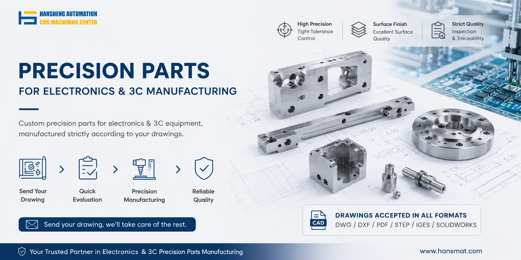
The nozzle is the key part that directly contacts the component. Surface wear can cause uneven suction distribution and tilt the component, while a partially blocked nozzle may reduce local vacuum and make pickup unstable. Flux or solder paste residue inside the nozzle can block the air hole and lower suction force. For non-standard nozzles or precision replacement parts used to maintain stable pickup, Hansheng Automation can provide custom machining according to customer drawings.
5. PCB deformation causing uneven contact surfaces
PCBs may bend or sag during processing or handling. If the deformation exceeds 0.5 mm, components may not fully contact the pads during placement. When the PCB has a concave area in the middle, the placement head follows a flat movement path, and the component may contact the pad on one side first, leading to side-standing. Local deformation can also cause uneven contact pressure between the nozzle and the component, further increasing the risk of flipping.
Side-standing and flipping are more common in small chip components such as 0603 and 0402 because their light weight and small size make them highly sensitive to placement parameters and equipment condition.
Recommended preventive measures
Set correct component height parameters in the placement software so that the placement head movement matches the actual component dimensions.
Adjust the Z-axis pickup height to avoid excessive pressure that causes feeder vibration.
Optimize the nozzle vacuum control program to synchronize vacuum opening and closing with placement motion.
Inspect nozzles regularly for wear and use dedicated cleaning tools to remove blockages.
Add support devices for deformed PCBs, such as custom fixtures or adjusted conveyor pressure, to keep the board surface flat and stable.